The AUX I/O connector allows the PXB to interface with external equipment by sending and/or receiving supplementary (auxiliary) signaling information, such as:
PXBs shipping after May 2013 have a 36-pin female AUX I/O connector and clock circuitry to support strobe functions. PXBs that shipped May 2013 or earlier have a 20-pin female AUX I/O connector. The 20-pin connector is compatible with Signal Studio real time applications; however, it doesn't support strobe-related functions.
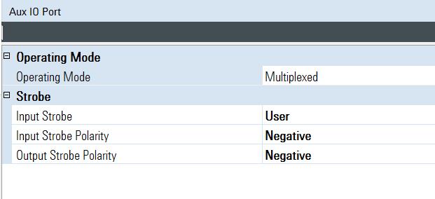
Choices: Multiplexed, Dedicated
Default Value: Multiplexed
Sets the AUX I/O Port operating mode.
Multiplexed
Configures the AUX I/O port operating mode to Multiplexed for real-time applications.
Dedicated
Configures the AUX I/O port operating mode to Dedicated for real-time applications.
Supported: PXB models with 36-pin AUX I/O connector
Choices: Free Run, User
Default Value: Free Run
Selects the AUX I/O port input strobe. In Dedicated operating mode, the instrument will always be in Free Run mode. If Multiplexed mode is selected, either Free Run or User input strobe mode can be selected.
Free Run
New input data is latched based on an internal clock.
User
A user-supplied strobe signal is used to latch data.
Supported: PXB models with 36-pin AUX I/O connector
Choices: Positive, Negative
Default Value: Positive
Select the polarity of the user external input strobe signal. This external input strobe signal must be at least 200 ns wide, and user must hold assert 16 input data bits stable 20 ns before the active edge of the user input strobe and hold the data stable for at least 100 ns after the active edge of the user input strobe.
Positive
A rising edge of the external strobe signal will latch the data.
Negative
A falling edge will latch the data.
Supported: PXB models with 36-pin AUX I/O connector
Choices: Positive, Negative
Default Value: Positive
Select the polarity of the AUX output sample clock. This signal indicates that the 16 input data bits have been latched and will be output in both Free Run and external input strobe mode. The output pulse will be at least 200 ns wide.
Positive
A pulse with a rising edge will be asserted to indicate when the 16 input data bits have been latched.
Negative
A pulse with a falling edge will be asserted to indicate when the 16 input data bits have been latched.