Marker files use one byte per I/Q waveform point to set the state of the markers either on (1) or off (0) for each I/Q point. When a marker is active (on), it provides an output trigger signal to the baseband generator block. Because markers are set at each waveform point, the marker file contains the same number of bytes as there are waveform points. For example, for 200 waveform points, the marker file contains 200 bytes.
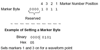
Although a marker point is one byte, the PXB uses only bits 0–3 to configure the markers; bits 4–7 are reserved and set to zero. The following example shows a marker byte.
The following example shows a marker binary file (all values in hex) for a waveform with 200 points. Notice the first marker point, 0f, shows all four markers on for only the first waveform point. The PXB provides for three markers at each point on the baseband generator waveform signal, Marker 1, Marker 3, and Marker 4. Marker 2 is not used by the PXB and will ignore attempts by the marker file to turn on Marker 2.
|
|
|
0f = All markers on (Markers 1, 3, and 4 on; Marker 2 is ignored) 01 = Marker 1 on 05 = Markers 1 and 3 on 04 = Marker 3 on 00 = No active markers |