Avionics
The Carrier tab allows you to view and configure the following settings based on the Avionics carrier types.
ILS Localizer - Carrier Freq Index
ILS Localizer - Left/Right - Left Frequency
ILS Localizer - Left/Right - Right Frequency
ILS Localizer - Left/Right - Left/Right Phase
ILS Localizer - DDM/SDM - DDM uA
ILS Localizer - DDM/SDM - DDM Percentage
ILS Glideslope - Carrier Freq Index
ILS Glideslope - Up/Down - Up Frequency
ILS Glideslope - Up/Down - Down Frequency
ILS Glideslope - Up/Down - Up/Down Phase
ILS Glideslope - DDM/SDM - Fly
ILS Glideslope - DDM/SDM - DDM
ILS Glideslope - DDM/SDM - DDM uA
ILS Glideslope - DDM/SDM - DDM Percentage
ILS Glideslope - DDM/SDM - SDM
Marker Beacon - Carrier Freq Index
Marker Beacon - Inner Marker Frequency
Marker Beacon - Middle Marker Frequency
Marker Beacon - Outer Marker Frequency
Selects the Avionics type.
|
SCPI Command |
[:SOURce]:RADio:AVIonics[:WAVeform]:TYPE VOR|ILSLocalizer|ILSGslope|MBEacon|TDME [:SOURce]:RADio:AVIonics[:WAVeform]:TYPE? |
|
SCPI Example |
RAD:AVI:TYPE VOR RAD:AVI:TYPE? |
| Choices | VOR | ILSLocalizer | ILSGslope | MBEacon | TDME |
|
Couplings |
|
|
Preset |
VOR |
|
State Saved |
Yes |
The following tabs are applicable when you select VOR as the Avionics Type.
VOR
Bearing
Ref
Selects the operating mode for the VOR modulation signal. The following options are available for the VOR Mode.
"NORM" VOR modulation is active.
"VAR" Amplitude modulation of the output signal with the VAR signal component (30 Hz signal content) of the VOR signal. The modulation depth corresponds to the value set for VOR - Ref - VAR Depth.
"Sub-carrier" Amplitude modulation of the output signal with the unmodulated FM carrier (9960 Hz) of the VOR signal. The modulation depth corresponds to the value set for VOR - Ref - Subcarrier Depth.
"Sub-carrier+FM" Amplitude modulation of the output signal with the frequency-modulated FM carrier (9960 Hz) of the VOR signal. The frequency deviation corresponds to the value set for VOR - Ref - REF Deviation and the modulation depth corresponds to the value set for VOR - Ref - Subcarrier Depth.
OFF - When you select OFF, all VOR signals are turned off and the Generate button is disabled.
|
SCPI Command |
[:SOURce]:RADio:AVIonics[:WAVeform]:VOR:MODE NORMal|VAR|SUBCarrier|SCFM|OFF [:SOURce]:RADio:AVIonics[:WAVeform]:VOR:MODE? |
|
SCPI Example |
RAD:AVI:VOR:MODE NORMal RAD:AVI:VOR:MODE? |
|
Couplings |
|
|
Preset |
NORMal |
|
State Saved |
Yes |
| Backwards Compatibility SCPI |
[:SOURce]:AVIonics:VOR:MODE OFF|NORMal|VAR|SUBCarrier|SBFM |
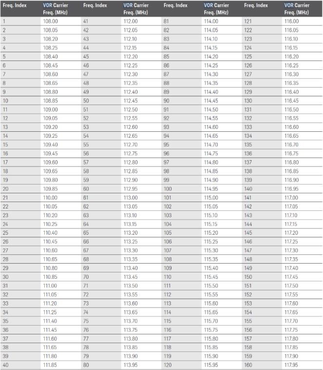
Sets the RF VOR Carrier Frequency based on the specified Carrier Frequency Index. The table below lists the Carrier Frequency Index and the applicable VOR Carrier frequency:.
|
SCPI Command |
[:SOURce]:RADio:AVIonics[:WAVeform]:VOR:FREQuency[:CARRier]:INDex <integer> [:SOURce]:RADio:AVIonics[:WAVeform]:VOR:FREQuency[:CARRier]:INDex? |
|
SCPI Example |
RAD:AVI:VOR:FREQ:INDex 10 RAD:AVI:VOR:FREQ:INDex? |
|
Couplings |
|
|
Preset |
1 |
|
State Saved |
Yes |
|
Min |
1 |
|
Max |
160 |
| Backwards Compatibility SCPI |
[:SOURce]:AVIonics:VOR:FREQuency[:CARRier]:INDex <integer> |
Sets the VOR Bearing Angle between the Variable Phase (VAR) and the Reference (REF) tones.
The orientation of the angle depends on the selected VOR - Bearing - Direction.
|
SCPI Command |
[:SOURce]:RADio:AVIonics[:WAVeform]:VOR:BEARing:ANGLe <real> [:SOURce]:RADio:AVIonics[:WAVeform]:VOR:BEARing:ANGLe? |
|
SCPI Example |
RAD:AVI:VOR:BEAR:ANGL 30 RAD:AVI:VOR:BEAR:ANGL? |
|
Couplings |
|
|
Preset |
0 deg |
|
State Saved |
Yes |
|
Min |
0 deg |
|
Max |
360 deg |
| Backwards Compatibility SCPI |
[:SOURce]:AVIonics:VOR:BEARing:ANGLe <real> |
Sets the reference position of the phase information. The angle set under "Bearing Angle" corresponds to the angle between the geographic north and the connection line from beacon to airplane.
A VOR instrument can be set to either a FROM or a TO convention.
From: Selection of the beacon as a reference position.
To: Selection of the airplane position as a reference position.
|
SCPI Command |
[:SOURce]:RADio:AVIonics[:WAVeform]:VOR:BEARing:DIRection FROM|TO [:SOURce]:RADio:AVIonics[:WAVeform]:VOR:BEARing:DIRection? |
|
SCPI Example |
RAD:AVI:VOR:BEAR:DIR FROM RAD:AVI:VOR:BEAR:DIR? |
|
Couplings |
|
|
Preset |
FROM |
|
State Saved |
Yes |
| Backwards Compatibility SCPI |
[:SOURce]:AVIonics:VOR:BEARing:DIRection FROM|TO |
Sets the frequency of the VAR signal and the REF signal. As the two signals must have the same frequency, the setting is valid for both signals.
|
SCPI Command |
[:SOURce]:RADio:AVIonics[:WAVeform]:VOR:FREQuency:REFVar <real> [:SOURce]:RADio:AVIonics[:WAVeform]:VOR:FREQuency:REFVar? |
|
SCPI Example |
RAD:AVI:VOR:FREQ:REFVar 30 RAD:AVI:VOR:FREQ:REFVar? |
|
Couplings |
|
|
Preset |
30 Hz |
|
State Saved |
Yes |
|
Min |
10 Hz |
|
Max |
60 Hz |
| Backwards Compatibility SCPI |
[:SOURce]:AVIonics:VOR:FREQuency:REFVar <real> |
Sets the amount of FM Deviation that the 30 Hz Reference (REF) tone causes on the sub-carrier for a VOR signal.
|
SCPI Command |
[:SOURce]:RADio:AVIonics[:WAVeform]:VOR:DEViation:REF <real> [:SOURce]:RADio:AVIonics[:WAVeform]:VOR:DEViation:REF? |
|
SCPI Example |
RAD:AVI:VOR:DEV:REF 30 RAD:AVI:VOR:DEV:REF? |
|
Couplings |
|
|
Preset |
480 Hz |
|
State Saved |
Yes |
|
Min |
0 Hz |
|
Max |
1000 Hz |
| Backwards Compatibility SCPI |
[:SOURce]:AVIonics:VOR:DEViation:REF <real> |
Sets the AM depth of the 30 Hz variable phase tone for a VOR signal.
|
SCPI Command |
[:SOURce]:RADio:AVIonics[:WAVeform]:VOR:DEPTh:VAR <real> [:SOURce]:RADio:AVIonics[:WAVeform]:VOR:DEPTh:VAR? |
|
SCPI Example |
RAD:AVI:VOR:DEPT:VAR 10 RAD:AVI:VOR:DEPT:VAR? |
|
Couplings |
|
|
Preset |
30 % |
|
State Saved |
Yes |
|
Min |
0 % |
|
Max |
49.9 % |
| Backwards Compatibility SCPI |
[:SOURce]:AVIonics:VOR:DEPTh:VAR <real>
|
Sets the frequency of the SUBCarrier for a VOR signal.
|
SCPI Command |
[:SOURce]:RADio:AVIonics[:WAVeform]:VOR:FREQuency:SUBCarrier <real> [:SOURce]:RADio:AVIonics[:WAVeform]:VOR:FREQuency:SUBCarrier? |
|
SCPI Example |
RAD:AVI:VOR:FREQ:SUBC 30 RAD:AVI:VOR:FREQ:SUBC? |
|
Couplings |
|
|
Preset |
9960 Hz |
|
State Saved |
Yes |
|
Min |
0 |
|
Max |
20000 Hz |
| Backwards Compatibility SCPI |
[:SOURce]:AVIonics:VOR:FREQuency:SUBCarrier <real> |
Sets the sub-carrier AM depth as it modulates the main carrier of a VOR signal.
|
SCPI Command |
[:SOURce]:RADio:AVIonics[:WAVeform]:VOR:DEPTh:SUBCarrier <real> [:SOURce]:RADio:AVIonics[:WAVeform]:VOR:DEPTh:SUBCarrier? |
|
SCPI Example |
RAD:AVI:VOR:DEPT:SUBC 30 RAD:AVI:VOR:DEPT:SUBC? |
|
Couplings |
|
|
Preset |
30 % |
|
State Saved |
Yes |
|
Min |
0 % |
|
Max |
49.9 % |
| Backwards Compatibility SCPI |
[:SOURce]:AVIonics:VOR:DEPTh:SUBCarrier <real> |
Presets the VOR settings to their factory-defined values.
This setting is available as SCPI command only.
|
SCPI Command |
[:SOURce]:RADio:AVIonics[:WAVeform]:VOR:PRESet |
|
SCPI Example |
RADio:AVIonics:VOR:PRESet |
|
Couplings |
|
|
Preset |
|
|
State Saved |
Yes |
| Backwards Compatibility SCPI |
[:SOURce]:AVIonics:VOR:PRESet |
The following tabs are applicable when you select ILS Localizer as the Avionics Type.
ILS Localizer
Left/Right
DDM/SDM
Allows selection of a complete or partial ILS Localizer signal and can set the ILS Localizer Mode to one of the following:
NORM | SLEFt (Suppress Left) | SRIGht (Suppress Right) | OFF
|
SCPI Command |
[:SOURce]:RADio:AVIonics[:WAVeform]:ILSLocalizer:MODE NORMal|SLEFt|SRIGht|OFF [:SOURce]:RADio:AVIonics[:WAVeform]:ILSLocalizer:MODE? |
|
SCPI Example |
RAD:AVI:ILSL:MODE NORMal RAD:AVI:ILSL:MODE? |
|
Couplings |
|
|
Preset |
NORMal |
|
State Saved |
Yes |
| Backwards Compatibility SCPI |
[:SOURce]:AVIonics:ILSLocalizer:MODE OFF|NORMal|SLEFt|SRIGht |
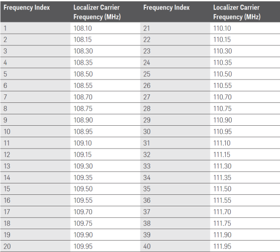
Used to select the RF Localizer frequencies. The following table displays the Localizer Carrier frequencies based on the Carrier Frequency Index.
|
SCPI Command |
[:SOURce]:RADio:AVIonics[:WAVeform]:ILSLocalizer:FREQuency[:CARRier]:INDex <integer> [:SOURce]:RADio:AVIonics[:WAVeform]:ILSLocalizer:FREQuency[:CARRier]:INDex? |
|
SCPI Example |
RAD:AVI:ILSL:FREQ:IND 20 RAD:AVI:ILSL:FREQ:IND? |
|
Couplings |
|
|
Preset |
1 |
|
State Saved |
Yes |
|
Min |
1 |
|
Max |
40 |
| Backwards Compatibility SCPI |
[:SOURce]:AVIonics:ILSLocalizer:FREQuency[:CARRier]:INDex <integer> |
Sets the frequency of the LEFT ILS Localizer signal.
|
SCPI Command |
[:SOURce]:RADio:AVIonics[:WAVeform]:ILSLocalizer:FREQuency:LEFT <real> [:SOURce]:RADio:AVIonics[:WAVeform]:ILSLocalizer:FREQuency:LEFT? |
|
SCPI Example |
RAD:AVI:ILSL:FREQ:LEFT 100 RAD:AVI:ILSL:FREQ:LEFT? |
|
Couplings |
|
|
Preset |
90 Hz |
|
State Saved |
Yes |
|
Min |
0 Hz |
|
Max |
120 Hz |
| Backwards Compatibility SCPI |
[:SOURce]:AVIonics:ILSLocalizer:FREQuency:LEFT <real> |
Sets the frequency of the RIGHt ILS Localizer signal.
|
SCPI Command |
[:SOURce]:RADio:AVIonics[:WAVeform]:ILSLocalizer:FREQuency:RIGHt <real> [:SOURce]:RADio:AVIonics[:WAVeform]:ILSLocalizer:FREQuency:RIGHt? |
|
SCPI Example |
RAD:AVI:ILSL:FREQ:RIGH 180 RAD:AVI:ILSL:FREQ:RIGH? |
|
Couplings |
|
|
Preset |
150 Hz |
|
State Saved |
Yes |
|
Min |
0 Hz |
|
Max |
200 Hz |
| Backwards Compatibility SCPI |
[:SOURce]:AVIonics:ILSLocalizer:FREQuency:RIGHt <real> |
Sets the phase of the right (150 Hz) ILS Localizer signal relative to the left (90 Hz) ILS Localizer signal.
|
SCPI Command |
[:SOURce]:RADio:AVIonics[:WAVeform]:ILSLocalizer:FLY:PHASe <real> [:SOURce]:RADio:AVIonics[:WAVeform]:ILSLocalizer:FLY:PHASe? |
|
SCPI Example |
RAD:AVI:ILSL:FLY:PHAS 180 RAD:AVI:ILSL:FLY:PHAS? |
|
Couplings |
|
|
Preset |
0 deg |
|
State Saved |
Yes |
|
Min |
0 deg |
|
Max |
360 deg |
| Backwards Compatibility SCPI |
[:SOURce]:AVIonics:ILSLocalizer:FLY:PHASe <real> |
Sets the “Difference in Depth of Modulation” (DDM) polarity of the ILS Localizer signal to either:
LEFT - positive
RIGHt - negative.
|
SCPI Command |
[:SOURce]:RADio:AVIonics[:WAVeform]:ILSLocalizer:FLY:DIRection LEFT|RIGHt [:SOURce]:RADio:AVIonics[:WAVeform]:ILSLocalizer:FLY:DIRection? |
|
SCPI Example |
RAD:AVI:ILSL:FLY:DIR LEFT RAD:AVI:ILSL:FLY:DIR? |
|
Couplings |
|
|
Preset |
LEFT |
|
State Saved |
Yes |
| Backwards Compatibility SCPI |
[:SOURce]:AVIonics:ILSLocalizer:FLY:DIRection LEFT|RIGHt |
DDM is defined to be the “percentage modulation depth of the larger signal” minus the “percentage modulation depth of the smaller signal”, divided by 100.
You can enter the values in DDM between the range -SDM/100 to SDM/100.
Depending upon the value entered in DDM, the value of DDM uA is calculated as DDM * 967.75 and the value of DDM percentage is calculated as DDM*100.
|
SCPI Command |
[:SOURce]:RADio:AVIonics[:WAVeform]:ILSLocalizer:DDM:DDM <real> [:SOURce]:RADio:AVIonics[:WAVeform]:ILSLocalizer:DDM:DDM? |
|
SCPI Example |
RAD:AVI:ILSL:DDM:DDM 0.45 RAD:AVI:ILSL:DDM:DDM? |
|
Couplings |
|
|
Preset |
0 |
|
State Saved |
Yes |
|
Min |
-0.99 |
|
Max |
0.99 |
| Backwards Compatibility SCPI |
[:SOURce]:AVIonics:ILSLocalizer:DDM:DDM <real> |
Sets a value for the difference in depth of modulation (DDM) in uA. You can enter the values in DDM uA between the range -SDM/100*967.75 to SDM/100*967.75.
Depending upon the value entered in DDM uA, the value of DDM is calculated as DDM uA/967.75 and the value of DDM percentage is calculated as DDM * 100.
|
SCPI Command |
[:SOURce]:RADio:AVIonics[:WAVeform]:ILSLocalizer:DDM:UAMPs <real> [:SOURce]:RADio:AVIonics[:WAVeform]:ILSLocalizer:DDM:UAMPs? |
|
SCPI Example |
RAD:AVI:ILSL:DDM:UAMP 500 RAD:AVI:ILSL:DDM:UAMP? |
|
Couplings |
If Fly Type is Right, then all the settings in DDM/SDM is positive and if the Fly Type is Left then all the settings in DDM/SDM is negative except SDM which is always positive. |
|
Preset |
0 uA |
|
State Saved |
Yes |
|
Min |
-958.1 uA |
|
Max |
958.1 uA |
| Backwards Compatibility SCPI |
[:SOURce]:AVIonics:ILSLocalizer:DDM:UAMPs <real> |
Sets a value for the difference in depth of modulation (DDM) in percent (%). You can enter the values in DDM Percentage between the range -SDM to SDM.
Depending upon the value entered in DDM Percentage, the value of DDM is calculated as DDM Percentage/100 and the value of DDM uA is calculated as DDM*967.75.
|
SCPI Command |
[:SOURce]:RADio:AVIonics[:WAVeform]:ILSLocalizer:DDM[:PERCent] <real> [:SOURce]:RADio:AVIonics[:WAVeform]:ILSLocalizer:DDM[:PERCent]? |
|
SCPI Example |
RAD:AVI:ILSL:DDM 90 RAD:AVI:ILSL:DDM? |
|
Couplings |
|
|
Preset |
0 % |
|
State Saved |
Yes |
|
Min |
-99 % |
|
Max |
99 % |
| Backwards Compatibility SCPI |
[:SOURce]:AVIonics:ILSLocalizer:DDM[:PERCent] <real> |
Sets the sum of depth of modulation (SDM) as:
SDM = [AM(90 Hz) + AM(150 Hz)] / 100.
|
SCPI Command |
[:SOURce]:RADio:AVIonics[:WAVeform]:ILSLocalizer:SDM <real> [:SOURce]:RADio:AVIonics[:WAVeform]:ILSLocalizer:SDM? |
|
SCPI Example |
RAD:AVI:ILSL:SDM 90 RAD:AVI:ILSL:SDM? |
|
Couplings |
|
|
Preset |
40 % |
|
State Saved |
Yes |
|
Min |
0 % |
|
Max |
99 % |
| Backwards Compatibility SCPI |
[:SOURce]:AVIonics:ILSLocalizer:SDM <real> |
Presets the ILS Localizer settings to the default values.
This setting is available as SCPI command only.
|
SCPI Command |
[:SOURce]:RADio:AVIonics[:WAVeform]:ILSLocalizer:PRESet |
|
SCPI Example |
RADio:AVIonics:ILSLocalizer:PRESet |
|
Couplings |
|
|
Preset |
|
|
State Saved |
Yes |
|
Min |
|
|
Max |
|
| Backwards Compatibility SCPI |
[:SOURce]:AVIonics:ILSLocalizer:PRESet |
The following subsections are applicable when you select ILS Glideslope as the Avionics Type.
ILS Glideslope
Up/Down
DDM/SDM
Allows selection of a complete or partial ILS Glide Slope signal and can set the ILS Glide Slope Mode to one of the following:
NORM | SUP (Suppress Up) | SDOWn (Suppress Down) | OFF
|
SCPI Command |
[:SOURce]:RADio:AVIonics[:WAVeform]:ILSGslope:MODE NORMal|SUP|SDOWn|OFF [:SOURce]:RADio:AVIonics[:WAVeform]:ILSGslope:MODE? |
|
SCPI Example |
RAD:AVI:ILSG:MODE NORMal RAD:AVI:ILSG:MODE? |
|
Couplings |
|
|
Preset |
NORMal |
|
State Saved |
Yes |
| Backwards Compatibility SCPI |
[:SOURce]:AVIonics:ILSGslope:MODE OFF|NORMal|SUP|SDOWn |
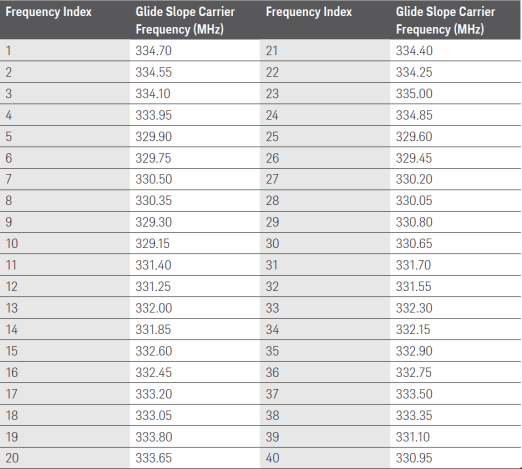
Used to select the RF Glideslope frequencies. The following table displays the Glide Slope Carrier frequencies based on the Carrier Frequency Index.
|
SCPI Command |
[:SOURce]:RADio:AVIonics[:WAVeform]:ILSGslope:FREQuency[:CARRier]:INDex <integer> [:SOURce]:RADio:AVIonics[:WAVeform]:ILSGslope:FREQuency[:CARRier]:INDex? |
|
SCPI Example |
RAD:AVI:ILSG:FREQ:IND 20 RAD:AVI:ILSG:FREQ:IND? |
|
Couplings |
|
|
Preset |
1 |
|
State Saved |
Yes |
|
Min |
1 |
|
Max |
40 |
| Backwards Compatibility SCPI |
[:SOURce]:AVIonics:ILSGslope:FREQuency[:CARRier]:INDex <integer> |
Sets the frequency of the Up ILS Glide Slope signal.
|
SCPI Command |
[:SOURce]:RADio:AVIonics[:WAVeform]:ILSGslope:FREQuency:UP <real> [:SOURce]:RADio:AVIonics[:WAVeform]:ILSGslope:FREQuency:UP? |
|
SCPI Example |
RAD:AVI:ILSG:FREQ:UP 100 RAD:AVI:ILSG:FREQ:UP? |
|
Couplings |
|
|
Preset |
90 Hz |
|
State Saved |
Yes |
|
Min |
0 Hz |
|
Max |
120 Hz |
| Backwards Compatibility SCPI |
[:SOURce]:AVIonics:ILSGslope:FREQuency:UP <real> |
Sets the frequency of the Down ILS Glide Slope signal.
Sets the phase of the Down (150 Hz) ILS Glide Slope signal relative to the Up (90 Hz) ILS Glide Slope signal.
|
SCPI Command |
[:SOURce]:RADio:AVIonics[:WAVeform]:ILSGslope:FLY:PHASe <real> [:SOURce]:RADio:AVIonics[:WAVeform]:ILSGslope:FLY:PHASe? |
|
SCPI Example |
RAD:AVI:ILSG:FLY:PHAS 200 RAD:AVI:ILSG:FLY:PHAS? |
|
Couplings |
|
|
Preset |
0 deg |
|
State Saved |
Yes |
|
Min |
0 deg |
|
Max |
360 deg |
| Backwards Compatibility SCPI |
[:SOURce]:AVIonics:ILSGslope:FLY:PHASe <real> |
Enables the adjustment of the aircraft to up or down correctly during landing.
|
SCPI Command |
[:SOURce]:RADio:AVIonics[:WAVeform]:ILSGslope:FLY:DIRection UP|DOWN [:SOURce]:RADio:AVIonics[:WAVeform]:ILSGslope:FLY:DIRection? |
|
SCPI Example |
RAD:AVI:ILSG:FLY:DIR UP RAD:AVI:ILSG:FLY:DIR? |
|
Couplings |
If Fly Type is Down, then all the settings in DDM/SDM is positive and if the Fly Type is Up then all the settings in DDM/SDM is negative except SDM which is always positive. |
|
Preset |
UP |
|
State Saved |
Yes |
| Backwards Compatibility SCPI |
[:SOURce]:AVIonics:ILSGslope:FLY:DIRection UP|DOWN |
DDM is defined to be the “percentage modulation depth of the larger signal” minus the “percentage modulation depth of the smaller signal”, divided by 100.
You can enter the values in DDM between the range -SDM/100 to SDM/100.
Depending upon the value entered in DDM, the value of DDM uA is calculated as DDM * 856.96 and the value of DDM percentage is calculated as DDM*100.
|
SCPI Command |
[:SOURce]:RADio:AVIonics[:WAVeform]:ILSGslope:DDM:DDM <real> [:SOURce]:RADio:AVIonics[:WAVeform]:ILSGslope:DDM:DDM? |
|
SCPI Example |
RAD:AVI:ILSG:DDM:DDM 0.45 RAD:AVI:ILSG:DDM:DDM? |
|
Couplings |
|
|
Preset |
0 |
|
State Saved |
Yes |
|
Min |
-0.99 |
|
Max |
0.99 |
| Backwards Compatibility SCPI |
[:SOURce]:AVIonics:ILSGslope:DDM:DDM <real> |
Sets a value for the difference in depth of modulation (DDM) in µA. You can enter the values in DDM uA between the range -SDM/100*856.96 to SDM/100*856.96.
Depending upon the value entered in DDM uA, the value of DDM is calculated as (DDM uA/856.96) and the value of DDM percentage is calculated as (DDM * 100).
|
SCPI Command |
[:SOURce]:RADio:AVIonics[:WAVeform]:ILSGslope:DDM:UAMPs <real> [:SOURce]:RADio:AVIonics[:WAVeform]:ILSGslope:DDM:UAMPs? |
|
SCPI Example |
RAD:AVI:ILSG:DDM:UAMP 840 RAD:AVI:ILSG:DDM:UAMP? |
|
Couplings |
|
|
Preset |
0 uA |
|
State Saved |
Yes |
|
Min |
-848.6 uA |
|
Max |
848.6 uA |
| Backwards Compatibility SCPI |
[:SOURce]:AVIonics:ILSGslope:DDM:UAMPs <real> |
Sets a value for the difference in depth of modulation (DDM) in %. You can enter the values in DDM Percentage between the range -SDM to SDM.
Depending upon the value entered in DDM Percentage, the value of DDM is calculated as (DDM Percentage/100) and the value of DDM uA is calculated as DDM*856.96.
|
SCPI Command |
[:SOURce]:RADio:AVIonics[:WAVeform]:ILSGslope:DDM[:PERCent] <real> [:SOURce]:RADio:AVIonics[:WAVeform]:ILSGslope:DDM[:PERCent]? |
|
SCPI Example |
RAD:AVI:ILSG:DDM 90 RAD:AVI:ILSG:DDM? |
|
Couplings |
|
|
Preset |
0 % |
|
State Saved |
Yes |
|
Min |
-99 % |
|
Max |
99 % |
| Backwards Compatibility SCPI |
[:SOURce]:AVIonics:ILSGslope:DDM[:PERCent] <real> |
Sets the sum of depth of modulation (SDM) as:
SDM = [AM(90 Hz) + AM(150 Hz)] / 100.
|
SCPI Command |
[:SOURce]:RADio:AVIonics[:WAVeform]:ILSGslope:SDM <real> [:SOURce]:RADio:AVIonics[:WAVeform]:ILSGslope:SDM? |
|
SCPI Example |
RAD:AVI:ILSG:SDM 75 RAD:AVI:ILSG:SDM? |
|
Couplings |
|
|
Preset |
80 % |
|
State Saved |
Yes |
|
Min |
0 % |
|
Max |
89 % |
| Backwards Compatibility SCPI |
[:SOURce]:AVIonics:ILSGslope:SDM <real> |
Presets the ILS Glideslope settings to their default values.
This setting is available as SCPI command only.
|
SCPI Command |
[:SOURce]:RADio:AVIonics[:WAVeform]:ILSGslope:PRESet |
|
SCPI Example |
RADio:AVIonics:ILSGslope:PRESet |
|
Couplings |
|
|
Preset |
|
|
State Saved |
Yes |
| Backwards Compatibility SCPI |
[:SOURce]:AVIonics:ILSGslope:PRESet |
The following tab is applicable when you select Marker Beacon as the Avionics Type.
Marker Beacon
Selects a Marker Beacon Mode. It can be one of the following:
INNer | MIDDle | OUTer | OFF
|
SCPI Command |
[:SOURce]:RADio:AVIonics[:WAVeform]:MBEacon:MODE INNer|MIDDle|OUTer|OFF [:SOURce]:RADio:AVIonics[:WAVeform]:MBEacon:MODE? |
|
SCPI Example |
RAD:AVI:MBE:MODE INNer RAD:AVI:MBE:MODE? |
|
Couplings |
|
|
Preset |
INNer |
|
State Saved |
Yes |
| Backwards Compatibility SCPI |
[:SOURce]:AVIonics:MBEacon:MODE OFF|INNer|MIDDle|OUTer |
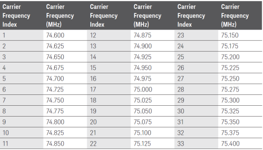
Used to select the RF Marker Beacon frequencies. The following table displays the Marker Beacon Carrier frequencies based on the Carrier Frequency Index.
|
SCPI Command |
[:SOURce]:RADio:AVIonics[:WAVeform]:MBEacon:FREQuency[:CARRier]:INDex <integer> [:SOURce]:RADio:AVIonics[:WAVeform]:MBEacon:FREQuency[:CARRier]:INDex? |
|
SCPI Example |
RAD:AVI:MBE:FREQ:IND 20 RAD:AVI:MBE:FREQ:IND? |
|
Couplings |
|
|
Preset |
17 |
|
State Saved |
Yes |
|
Min |
1 |
|
Max |
33 |
| Backwards Compatibility SCPI |
[:SOURce]:AVIonics:MBEacon:FREQuency[:CARRier]:INDex <integer>
|
Sets the frequency for the Inner Marker Beacon.
|
SCPI Command |
[:SOURce]:RADio:AVIonics[:WAVeform]:MBEacon:FREQuency:INNer <real> [:SOURce]:RADio:AVIonics[:WAVeform]:MBEacon:FREQuency:INNer? |
|
SCPI Example |
RAD:AVI:MBE:FREQ:INN 400 RAD:AVI:MBE:FREQ:INN? |
|
Couplings |
Displayed only when the Inner Marker Beacon Mode is selected. |
|
Preset |
3000 Hz |
|
State Saved |
Yes |
|
Min |
0 Hz |
|
Max |
20000 Hz |
| Backwards Compatibility SCPI |
[:SOURce]:AVIonics:MBEacon:FREQuency:INNer <real> |
Sets the frequency for the Middle Marker Beacon.
|
SCPI Command |
[:SOURce]:RADio:AVIonics[:WAVeform]:MBEacon:FREQuency:MIDDle <real> [:SOURce]:RADio:AVIonics[:WAVeform]:MBEacon:FREQuency:MIDDle? |
|
SCPI Example |
RAD:AVI:MBE:FREQ:MIDD 1500 RAD:AVI:MBE:FREQ:MIDD? |
|
Couplings |
Displayed only when the Middle Marker Beacon Mode is selected. |
|
Preset |
1300 Hz |
|
State Saved |
Yes |
|
Min |
0 Hz |
|
Max |
20000 Hz |
| Backwards Compatibility SCPI |
[:SOURce]:AVIonics:MBEacon:FREQuency:MIDDle <real>
|
Sets the frequency for the Outer Marker Beacon.
|
SCPI Command |
[:SOURce]:RADio:AVIonics[:WAVeform]:MBEacon:FREQuency:OUTer <real> [:SOURce]:RADio:AVIonics[:WAVeform]:MBEacon:FREQuency:OUTer? |
|
SCPI Example |
RAD:AVI:MBE:FREQ:OUT 1000 RAD:AVI:MBE:FREQ:OUT? |
|
Couplings |
Displayed only when the Outer Marker Beacon Mode is selected. |
|
Preset |
400 Hz |
|
State Saved |
Yes |
|
Min |
0 Hz |
|
Max |
20000 Hz |
| Backwards Compatibility SCPI |
[:SOURce]:AVIonics:MBEacon:FREQuency:OUTer <real>
|
Sets the AM depth on the Marker Beacon carrier.
|
SCPI Command |
[:SOURce]:RADio:AVIonics[:WAVeform]:MBEacon:DEPTh <real> [:SOURce]:RADio:AVIonics[:WAVeform]:MBEacon:DEPTh? |
|
SCPI Example |
RAD:AVI:MBE:DEPT 98 RAD:AVI:MBE:DEPT? |
|
Couplings |
|
|
Preset |
95 % |
|
State Saved |
Yes |
|
Min |
0 % |
|
Max |
99.9 % |
| Backwards Compatibility SCPI |
[:SOURce]:AVIonics:MBEacon:DEPTh <real>
|
Presets the Marker Beacon settings to their default values.
This setting is available as SCPI command only.
|
SCPI Command |
[:SOURce]:RADio:AVIonics[:WAVeform]:MBEacon:PRESet |
|
SCPI Example |
RADio:AVIonics:MBEacon:PRESet |
|
Couplings |
|
|
Preset |
|
|
State Saved |
Yes |
| Backwards Compatibility SCPI |
[:SOURce]:AVIonics:MBEacon:PRESet |
The following tab is available when you select TDME as the Avionics Type.
TDME
Sets the Pulse Type to one of the following two options:
Singlet - There is only a single pulse. Therefore, the Intra Pulse Spacing is not applicable when you set Pulse Type to Singlet.
Doublet - There are two pulses.
|
SCPI Command |
[:SOURce]:RADio:AVIonics[:WAVeform]:TDME:PULSe:TYPE SINGlet|DOUBlet [:SOURce]:RADio:AVIonics[:WAVeform]:TDME:PULSe:TYPE? |
|
SCPI Example |
RADio:AVIonics:TDME:PULSe:TYPE DOUBlet RADio:AVIonics:TDME:PULSe:TYPE? |
|
Couplings |
|
|
Preset |
DOUBlet |
|
State Saved |
Yes |
| Backwards Compatibility SCPI |
[:SOURce]:RADio[1]:TDME:ARB:PULSe:TYPE {SINGlet}|DOUBlet |
Sets Intra Pulse Spacing which is the space between two pulses.
|
SCPI Command |
[:SOURce]:RADio:AVIonics[:WAVeform]:TDME:IPULse:SPACing <real> [:SOURce]:RADio:AVIonics[:WAVeform]:TDME:IPULse:SPACing? |
|
SCPI Example |
RADio:AVIonics:TDME:IPULse:SPACing 0.000013 RADio:AVIonics:TDME:IPULse:SPACing? |
|
Couplings |
|
|
Preset |
12 us |
|
State Saved |
Yes |
| Min | 12 us |
| Max | 36 us |
| Backwards Compatibility SCPI |
[:SOURce]:RADio[1]:TDME:ARB:IPULse:SPACing <spacing seconds> |
Sets Pulse Repetition Frequency which represents the number of pulse pairs per second.
|
SCPI Command |
[:SOURce]:RADio:AVIonics[:WAVeform]:TDME:PRFrequency <real> [:SOURce]:RADio:AVIonics[:WAVeform]:TDME:PRFrequency? |
|
SCPI Example |
RADio:AVIonics:TDME:PRFrequency 300 RADio:AVIonics:TDME:PRFrequency? |
|
Couplings |
|
|
Preset |
100 Hz |
|
State Saved |
Yes |
| Min | 100 Hz |
| Max | 400 Hz |
| Backwards Compatibility SCPI |
[:SOURce]:RADio[1]:TDME:ARB:PRFrequency<pulseRepetitionFrequencyHz> |
Sets TDME Rise time which is the time required for a signal to rise from 10% to 90% of its amplitude.
|
SCPI Command |
[:SOURce]:RADio:AVIonics[:WAVeform]:TDME:RTIMe <real> [:SOURce]:RADio:AVIonics[:WAVeform]:TDME:RTIMe? |
|
SCPI Example |
RADio:AVIonics:TDME:RTIMe 0.000003 RADio:AVIonics:TDME:RTIMe? |
|
Couplings |
|
|
Preset |
2.5 us |
|
State Saved |
Yes |
| Min | 0.8 us |
| Max | 3 us |
| Backwards Compatibility SCPI |
[:SOURce]:RADio[1]:TDME:ARB:RTIMe <timeSec> |
Sets TDME Fall time which is the time required for a signal to decay from 90% down to 10% of its amplitude.
|
SCPI Command |
[:SOURce]:RADio:AVIonics[:WAVeform]:TDME:FTIMe <real> [:SOURce]:RADio:AVIonics[:WAVeform]:TDME:FTIMe? |
|
SCPI Example |
RADio:AVIonics:TDME:FTIMe 0.000003 RADio:AVIonics:TDME:FTIMe? |
|
Couplings |
|
|
Preset |
2.5 us |
|
State Saved |
Yes |
| Min | 0.8 us |
| Max | 3 us |
| Backwards Compatibility SCPI |
[:SOURce]:RADio[1]:TDME:ARB:FTIMe <timeSec> |
Returns the TDME Width FWHM which is the width of a pulse between two points where the amplitude is 50% of its maximum value.
|
SCPI Command |
[:SOURce]:RADio:AVIonics[:WAVeform]:TDME:PULSe:WIDTH? |
|
SCPI Example |
RADio:AVIonics:TDME:PULSe:WIDTH? |
|
Couplings |
|
|
Preset |
3.49 us |
|
State Saved |
Yes |
| Min | 0 |
| Max | 1 |
| Backwards Compatibility SCPI |
[:SOURce]:RADio[1]:TDME:ARB:PULSe:WIDTH? |
The following settings are applicable for the COM/ID tab and are used to configure the COM/ID settings.
COM/ID
COM//ID Type
COM/ ID Code
Frequency
Depth
Period
Toggles COM/ID OFF (0) or ON (1). OFF (0) - all COM/ID functions are turned off.
|
SCPI Command |
[:SOURce]:RADio:AVIonics[:WAVeform]:CID[:STATe] 1|0 [:SOURce]:RADio:AVIonics[:WAVeform]:CID[:STATe]? |
|
SCPI Example |
RAD:AVI:CID 0 RAD:AVI:CID? |
|
Couplings |
|
|
Preset |
OFF |
|
State Saved |
Yes |
| Backwards Compatibility SCPI |
[:SOURce]:AVIonics:CID[:STATe] OFF|ON|0|1 |
Toggles the COM/ID Type.
Code - When set to CODE, the signal generator plays the code associated with the COM/ID Code.
Tone - When set to TONE, the COM/ID Code setting is disabled and the signal generator plays a continuous tone based on the COM/ID Frequency setting.
|
SCPI Command |
[:SOURce]:RADio:AVIonics[:WAVeform]:CID:TYPE CODE|TONE [:SOURce]:RADio:AVIonics[:WAVeform]:CID:TYPE? |
|
SCPI Example |
RAD:AVI:CID:TYPE CODE RAD:AVI:CID:TYPE? |
|
Couplings |
When COM/ID Type is set to TONE then Period Setting is disabled. Period Setting is displayed when COM/ID Type is set to CODE. |
|
Preset |
CODE |
|
State Saved |
Yes |
| Backwards Compatibility SCPI |
[:SOURce]:AVIonics:CID:TYPE CODE|TONE |
Specify a valid COM/ID code (airport identification code) by typing a 3-character code enclosed in single-quotes or double-quotes (for example, ‘STS’ or “STS”). COM/ID Code is set to default value i.e STS.
COM/ID Code:
Cannot contain more than 3 characters
Ccharacters should be only [a-z] [A-Z]
Numbers are not allowed in the COMID Code.
Example: If you specify a value ‘abc’ in the COM/ID Code and then change the value to ‘ab1’ then it should hold the previous value i.e ‘abc’ because the combination of characters and alphabets are not allowed.
|
SCPI Command |
[:SOURce]:RADio:AVIonics[:WAVeform]:CID:CODE [:SOURce]:RADio:AVIonics[:WAVeform]:CID:CODE? |
|
SCPI Example |
RAD:AVI:CID:CODE RAD:AVI:CID:CODE? |
|
Couplings |
When COM/ID Type is set to TONE then the COM/ID Code Setting is read only. |
|
Preset |
STS |
|
State Saved |
Yes |
| Backwards Compatibility SCPI |
[:SOURce]:AVIonics:CID:CODE <quoted 3-letter airport id> |
Sets the COM/ID tone or code modulating frequency.
|
SCPI Command |
[:SOURce]:RADio:AVIonics[:WAVeform]:CID:FREQuency <real> [:SOURce]:RADio:AVIonics[:WAVeform]:CID:FREQuency? |
|
SCPI Example |
RAD:AVI:CID:FREQ 5000 RAD:AVI:CID:FREQ? |
|
Couplings |
|
|
Preset |
1020 Hz |
|
State Saved |
Yes |
|
Min |
0 Hz |
|
Max |
20000 Hz |
| Backwards Compatibility SCPI |
[:SOURce]:AVIonics:CID:FREQuency <real> |
Sets the COM/ID tone AM depth.
|
SCPI Command |
[:SOURce]:RADio:AVIonics[:WAVeform]:CID:DEPTh <real> [:SOURce]:RADio:AVIonics[:WAVeform]:CID:DEPTh? |
|
SCPI Example |
RAD:AVI:CID:DEPT 40 RAD:AVI:CID:DEPT? |
|
Couplings |
|
|
Preset |
10 % |
|
State Saved |
Yes |
|
Min |
0 % |
|
Max |
49.9 % |
| Backwards Compatibility SCPI |
[:SOURce]:AVIonics:CID:DEPTh <real> |
Sets the period of the COM/ID signal in seconds. The default value of this setting is 2.6 s.
There is a relation between the morse length and this Period setting. For example, if you specify STS in the COM/ID Code, its morse length is 2.2 s and that is the minimum value of Period.
You can specify any value greater than 2.2 s. The value less than 2.2 sec is not permitted. If you specify a value less than 2.2 sec, the value will be automatically set to the minimum required value.
|
SCPI Command |
[:SOURce]:RADio:AVIonics[:WAVeform]:CID:PERiod <real> [:SOURce]:RADio:AVIonics[:WAVeform]:CID:PERiod? |
|
SCPI Example |
RAD:AVI:CID:PER 10 RAD:AVI:CID:PER? |
|
Couplings |
|
|
Preset |
2.6 s |
|
State Saved |
Yes |
|
Min |
1 s |
|
Max |
20 s |
Presets the COM/ID settings to their default values.
This setting is available as SCPI command only.
|
SCPI Command |
[:SOURce]:RADio:AVIonics[:WAVeform]:CID:PRESet |
|
SCPI Example |
RADio:AVIonics:CID:PRESet |
|
Couplings |
|
|
Preset |
|
|
State Saved |
Yes |
| Backwards Compatibility SCPI |
[:SOURce]:AVIonics:CID:PRESet |