Compressed Mode
Use of a compressed mode (Slotted Mode) is necessary when making measurements on another frequency (inter-frequency) or on a different radio technology (inter-RAT). In the Compressed Mode, while the transmission and reception are stopped for a short time, the measurements are performed on another frequency or Radio Access Technology (RAT) during the transmission and reception stop time. After the stop time is over, the transmission and reception resumes. To ensure that the data is not lost, the data is compressed in the frame, creating empty space where the measurements can be performed.
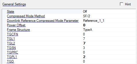
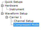
Click in the  tree view to access parameters in the General Settings table. The
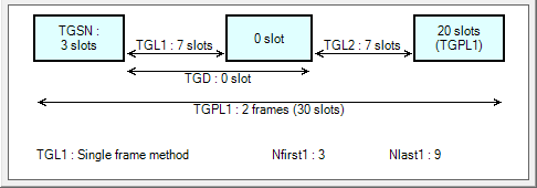
  diagram below the table updates as you make changes to the configuration.
Compressed mode is only available for the Advanced W-CDMA/HSPA+ Downlink Release 10 carrier.

General Settings
State
Choice: Off | On
Default: Off
Turns the DPCH compressed mode on or off. When DPCH compressed mode is on, ALC will turn off and only 1 DPCH channel is active. The timing offset for the DPCH channel is supported when compressed mode is on.
Compressed Mode Method
Choice: SF/2 | Higher Layer
Default: SF/2
Sets the DPCH compressed mode method. When set to Higher Layer, transport layer coding is supported with the Transport Position choice of Flexible.
Downlink Reference Compressed Mode Parameter
Choice: Reference Parameter 1.1 | Reference Parameter 1.2 | Reference Parameter 2.1 | Reference Parameter 2.2
Default: Reference Parameter 1.1
Sets the downlink reference compressed mode parameter defined in 3GPP standard TS25.101.
Power Offset
Range: 0 to 6
Default: 0
Sets the power offset (dB) for the compressed frame.
Frame Structure
Choice: TypeA | TypeB
Default: TypeA
Selects the frame structure type.
TGCFN
Range: 0 to 255
Default: 0
Sets the connection frame number (CFN) of the first radio frame of the first pattern within the transmission gap pattern.
TGL1
Choice: 3 | 4 | 5 | 7 | 10 | 14
Default: 7
Sets the TGL1 value, expressed in number of slots.
TGL2
Choice: 0 (TGL2=TGL1) | 3 | 4 | 5 | 7 | 10 | 14
Default: 0 (TGL2=TGL1)
Sets the TGL2 value, expressed in number of slots. If the value is set to 0 (omitted), then TGL2 = TGL1.
TGSN
Range: 0 to 14
Default: 3
Sets the transmission gap starting slot number (TGSN). TGSN is the slot number of the first transmission gap slot in the first radio frame of the transmission gap pattern.
TGPRC
Choice: 0 (infinite) to 511
Default: 0 (infinite)
Sets the number of transmission gap patterns in the transmission gap pattern sequence. Set TGPRC to 0 for infinite pattern repetition.
TGPL1
Range: 1 to 144
Default: 2
Sets the transmission gap pattern length (TGPL1), expressed in number of frames.
TGD
Range: 0 (undefined), 15 to 269
Default: 0 (undefined)
Sets the transmission gap start distance (TGD), which is the duration between the starting slots of two consecutive transmission gaps within a transmission gap pattern, expressed in number of slots. If TGD = 0, then only one transmission gap is available in the transmission gap pattern.

