Understanding the Cubic Metric

Cubic Metric (CM) is the metric of the of the actual reduction in power capability, or power de-rating, of a typical power amplifier in a mobile handset. This is a more effective predictor than the peak-to-average power ratio (PAR).
In amplifier circuits, the primary cause of adjacent channel (± 5MHz) ACLR is the third order non-linearity of the amplifier's gain characteristic. Ignoring any other causes of non-linearity, the amplifier voltage gain characteristics may be written as:

The G1 value
is the linear gain of the amplifier, while the G3
value is the non-linear gain. These values depend only on the amplifier
design, and will not change regardless of the signal used for  .
.
Given that the signal for  is
a 3GPP modulated RF carrier, then the cubic term above will generate several
types of degradation to the output signal. On-channel distortion terms
that contribute to EVM will be produced, as well as signals at the third
harmonic of the carrier frequency, and signals in the upper and lower
adjacent channel bands. For a given amplifier, the total energy in the
cubic term will be determined only by the
  signal, and this total energy will be distributed
among the various distortion components in some predefined, signal dependent
way.
In order to generate a metric that reflects the power in the cubic term above, the given voltage signal is first normalized to an rms value of 1.0, then cubed. The rms value of this cubed waveform is then computed and converted to dB.
Calculating the Cubic Metric
Cubic Metric is based on the UE transmit channel configuration, and is given by:
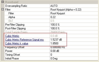
CM = CEIL{[20*log10((v_norm3)rms)–20*log10((v_norm_ref3)rms)]/k,0.5}
-
CEIL{x,0.5} is the value of the expression rounded upward to the closest 0.5 dB.
For example, CM = [0, 0.5, 1.0, 1.5, 2.0, 2.5, 3.0, 3.5]
-
k:
-
1.8500 for signals where all channelization codes meet the following criteria: CSF, N where N < SF/2
-
1.5600 for signals where any channelization codes meet the following criteria CSF, N where N > SF/2
For example, using Sub-tests 2 and 4 where N=1, E-DPDCH SF =4, E-DPDCH channelization code (C) =4.
-
Sub-tests 2 and 4 where N = 1, E-DPDCH SF = 4, E-DPDCH channelization code (C) = 4, N > 4/2
Since N = 1, 1
-
-
1.5600 for Sub-tests 2 and 4
-
-
v_norm3 is the normalized voltage waveform of the input signal.
-
v_norm_ref3 is the normalized voltage waveform of the reference signal (12.2 kbps AMR Speech) and
20*log10((v_norm_ref3)rms) = 1.5237 dB
For more information, see: