DPDCH
The Dedicated Physical Data Channel (DPDCH) transmits the higher layer information (e.g. user data, ...).
See also, DCH.
|
1. DPDCH |
2. DPDCH Data |
3. Transport Channel BER |
|---|---|---|
|
|
||
|
|
|
|
|
|
|
|
|
|
|
|
|
|
|
DPDCH Configuration Summary Table
This section defines the Settings Current and Apply Needed buttons. Only one button is available at any time. These buttons are available in all of the W-CDMA/HSPA+ Uplink's tree nodes.
|
|
This button indicates that the current real-time settings have been applied to the instrument. No action is required. |
|
This button indicates that the instrument settings are not current and need to be updated to be applied to the instrument. Click this button to update the instrument's settings. [:SOURce]:RADio:WCDMa:TGPP[:BBG]:ULINk:APPLy [:SOURce]:RADio:WCDMa:TGPP[:BBG]:ULINk:APPLy? |
1. DPDCH
State
Choice: Off | On
Default: On
Enables or disables the DPDCH state.
[:SOURce]:RADio:WCDMa:TGPP[:BBG]:ULINk:DPDCh[:STATe] ON|OFF|1|0
[:SOURce]:RADio:WCDMa:TGPP[:BBG]:ULINk:DPDCh[:STATe]?
Power
Range: –40 to 0 dB
Default: 0 dB
Enter the DPDCH power level in dB.
If the parameter set by the following command is changed while the signal is active, the :ULINk:APPLy command, Apply Needed ( ) button must be executed for the change to occur.
[:SOURce]:RADio:WCDMa:TGPP[:BBG]:ULINk:DPDCh:POWer <val>
[:SOURce]:RADio:WCDMa:TGPP[:BBG]:ULINk:DPDCh:POWer?
Channel Code
Range: 0 to 255
Default: 16
Sets the channel code of DPDCH. This field is enabled when only the DPCCh and/or DPDCH states are set to On. Indicates the calculated channel code of DPDCH when other channel states are set to On.
If the parameter set by the following command is changed while the signal is active, the :ULINk:APPLy command, Apply Needed ( ) button must be executed for the change to occur.
[:SOURce]:RADio:WCDMa:TGPP[:BBG]:ULINk:DPDCh:CCODe <val>
[:SOURce]:RADio:WCDMa:TGPP[:BBG]:ULINk:DPDCh:CCODe?
Slot Format
Range: 0 to 6
Default: 2
Sets the slot format of DPDCH. This value is coupled to Symbol Rate.
If the parameter set by the following command is changed while the signal is active, the :ULINk:APPLy command, Apply Needed ( ) button must be executed for the change to occur.
[:SOURce]:RADio:WCDMa:TGPP[:BBG]:ULINk:DPDCh:SLOTformat <val>
[:SOURce]:RADio:WCDMa:TGPP[:BBG]:ULINk:DPDCh:SLOTformat?
Symbol Rate
Selection: 15 ksps | 30 ksps | 60 ksps | 120 ksps | 240 ksps | 480 ksps | 960 ksps
Default: 60 ksps
Sets the Symbol Rate (symbol per second: sps) for DPDCH. This value is coupled to Slot Format.
If the parameter set by the following command is changed while the signal is active, the :ULINk:APPLy command, Apply Needed ( ) button must be executed for the change to occur.
[:SOURce]:RADio:WCDMa:TGPP[:BBG]:ULINk:DPDCh:RATE <val>
[:SOURce]:RADio:WCDMa:TGPP[:BBG]:ULINk:DPDCh:RATE?
Spreading Factor
Indicates the Spreading Factor for DPDCH. This parameter is not editable.
Nmax-dpdch
Choice: 0 | 1
Default: 1
Sets the maximum number of DPDCH (Nmax-dpdch) to control channel assignment.
This field is available when the DPDCH State is Off. When DPDCH State is On, this field is always 1.
If the parameter set by the following command is changed while the signal is active, the :ULINk:APPLy command, Apply Needed ( ) button must be executed for the change to occur.
[:SOURce]:RADio:WCDMa:TGPP[:BBG]:ULINk:NMDPdch 0|1
[:SOURce]:RADio:WCDMa:TGPP[:BBG]:ULINk:NMDPdch?
2. DPDCH Data
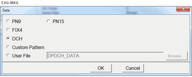
Data
Choice: PN9 | PN15 | FIX4 | DCH|Custom Pattern| User File
Default: DCH
Edit the Data for the dedicated physical data channel (DPDCH) by clicking on the cell. Then click on the dialog box icon  to launch the
  Data dialog box.
When loading a user file through the software's Data dialog box, the MXG/EXG requires an ASCII text file consisting of 1s and 0s. When using SCPI commands, all instruments require a binary data file.
If the parameter set by the following command is changed while the signal is active, the :ULINk:APPLy command, Apply Needed ( ) button must be executed for the change to occur.
[:SOURce]:RADio:WCDMa:TGPP[:BBG]:ULINk:DPDCh:DATA PN9|PN15|FIX4|DCH|"<filename>"|TRANspch|PATTern
[:SOURce]:RADio:WCDMa:TGPP[:BBG]:ULINk:DPDCh:DATA?
If you select <"filename">, PATTern or FIX4, use the following commands to create the pattern:
[:SOURce]:RADio:WCDMa:TGPP[:BBG]:ULINk:DPDCh:DATA:FIX4 <val>
[:SOURce]:RADio:WCDMa:TGPP[:BBG]:ULINk:DPDCh:DATA:FIX4?
[:SOURce]:RADio:WCDMa:TGPP[:BBG]:ULINk:DPDCh:DATA:PATTern <val>
[:SOURce]:RADio:WCDMa:TGPP[:BBG]:ULINk:DPDCh:DATA:PATTern?
Number of DCH
Range: 1 to 6
Default: 2
Sets the number of DCH for DPDCH coding source.
If the parameter set by the following command is changed while the signal is active, the :ULINk:APPLy command, Apply Needed ( ) button must be executed for the change to occur.
If you are using DCH, the following command enables or disables each DCHn. There is no SCPI command for directly choosing the Number of DCH.
[:SOURce]:RADio:WCDMa:TGPP[:BBG]:ULINk[:TGRoup[1]]:DCH[1]| 2|3|4|5|6[:STATe] ON|OFF|1|0
[:SOURce]:RADio:WCDMa:TGPP[:BBG]:ULINk[:TGRoup[1]]:DCH[1]| 2|3|4|5|6[:STATe]?
3. Transport Channel BER
Transport Channel BER
Range: 0.000000 to 1.000000
Default: 0.000000
Shows the value of the DPDCh Transport channel BER. This value is calculated by the DPDCH Transport channel BER cycle length and error insertion length.
Transport Channel BER Cycle Length
Range: 0 to 65535
Default: 0
Sets the cycle length of the DPDCh Transport channel BER.
[:SOURce]:RADio:WCDMa:TGPP[:BBG]:ULINk:DPDCh:TBER[:CLENgth] <val>
[:SOURce]:RADio:WCDMa:TGPP[:BBG]:ULINk:DPDCh:TBER[:CLENgth]?
Transport Channel BER Error Insertion Length
Range: 0 to 4095
Default: 0
Sets the error insertion length of the DPDCH Transport channel BER.
[:SOURce]:RADio:WCDMa:TGPP[:BBG]:ULINk:DPDCh:TBER:ELENgth <val>

