Data Setup Dialog Boxes (PRACH)
This topic explains the data setup dialog boxes and their parameters for the Message and RACH nodes. When configuring the data for timeslots that have a data entry, each timeslot's data setup dialog box is separate and independent of the other timeslots. Access to these dialog boxes is through the following nodes and settings:
|
Setting |
|
|---|---|
|
Message |
|
|
|
|
|
|
|
|
RACH |
|
|
|||||
|
|
|
||||
|
|
|
|
|||
|
|
|
|
|||
|
|
|
|
|
||
|
|
|
|
|
||
|
|
|
|
|
||
|
|
|
|
|
||
|
|
|
|
|
||
|
|
|
|
|
||
|
|
|
|
|
||
Data Setup Dialog Boxes
Typical Data Setup
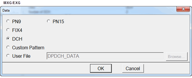
This is typically the dialog box shown when PN sequences are part of the data selections. Select to expand the dialog box to create a custom bit pattern. Please note that some choices may not be available on all of the data dialog boxes.

Custom Pattern Only Selection
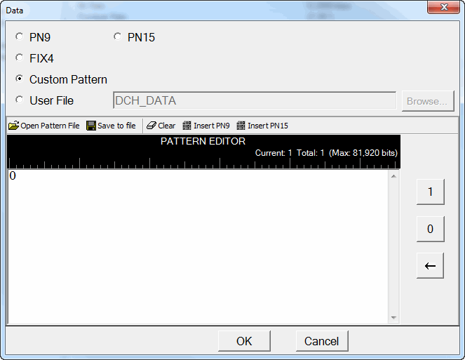
This is the dialog box shown when Custom Pattern is selected. Select to expand the dialog box to create a custom training sequence.

TFCI Data
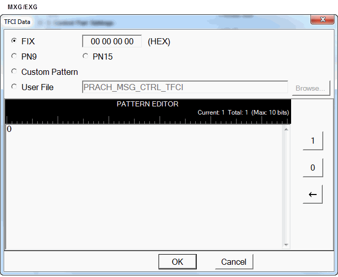
This is the dialog box shown when TFCI Data is selected in the Message node. TFCI Data sets a bit pattern to be inserted into the transport format combination indicator (TFCI) from 0 to 1023 (0x3FF). This value is encoded when "FIX" is selected, otherwise the assigned value is used without encoding. This parameter is used when the Data parameter in the Control Part Settings is set to "Standard". For the User File selection, the data file must be the text format and consist of '0' and/or '1' characters.

Selections
Each data selection lists the links to the SCPI commands, where applicable, that also makes the data selection. The links use the setting name (cell name) that accesses the data setup dialog box. When clicked, the links go to the topic with the setting description that includes the SCPI command. For a complete listing of the nodes and settings that use this topic, see the node and setting table at the top.
Standard
Selects the data type where the data is based on the 3GPP standards.
PN9 | PN15 | FIX4
These selections generate a pseudo-random bit pattern in accordance with the ITU standard for the selected PN sequence or and on a 4-bit binary.
Message
RACH
is not a data choice when channel coding is turned on for Normal GMSK and Normal 8PSK timeslots.
Custom Pattern
This selection opens the Pattern Editor with related buttons that lets you customize the transmitted data using up to 128,000 bits.
When the data setup dialog box is launched , it only shows the preselected selection and the Pattern Editor.
Message Control Part Settings: Data SCPI Command — select Pattern from the command choices
TFCI Data SCPI Command — select Pattern from the command choices
Message Data Part Settings: Data SCPI Command — select Pattern from the command choices
RACH: Data SCPI Command — select Pattern from the command choices
User File
Select this choice to load a predefined and saved custom data file. When selected, the button becomes active.
To use all of the data in the file, the file must supply enough bits to fill the desired number of timeslots (the same timeslot in multiple frames). When there are not enough bits remaining in the file to fill a timeslot, the remaining bits are ignored and the software reuses the file from the beginning. For example, if the timeslot requires 114 data bits and there is a need to fill the timeslot over 10 frames, then the minimum file size would be 1,140 bits. If the file size was only 1,000 bits, the data would be parsed over eight frames. On the ninth frame, the software would ignore the remaining 88 bits and reuse the file from the beginning.
When loading a user file through the software's Data dialog box, the MXG/EXG requires an ASCII text file consisting of 1s and 0s. When using SCPI commands, all instruments require a binary data file.
Message Control Part Settings: Data SCPI Command — select "<file name"> from the command choices
TFCI Data SCPI Command — select "<file name"> from the command choices
Message Data Part Settings: Data SCPI Command — select "<file name"> from the command choices
RACH: Data SCPI Command — select "<file name"> from the command choices
Button
For buttons associated with the Pattern Editor, see Pattern Editor Buttons.
Browse
Coupling: This button is enabled with the selection.
Click this button to open the dialog box to navigate to and select a previously configured and saved custom data file.
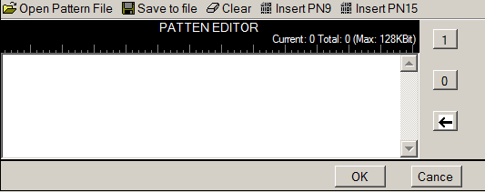
Pattern Editor
Use the PATTERN EDITOR to create custom bit patterns.The  PATTERN EDITOR area contains buttons to open, save, or clear user data along with the ability to insert PN9 or PN 15 data.
There are multiple ways to insert data:
-
using the 1 and 0 keys on the keyboard
-
using the Insert PN9 or Insert PN15 buttons
-
load a pattern file
-
use the 1 and 0 buttons on the PATTERN EDITOR
-
pasting data from a file or from within the current view
(The keyboard shortcuts Cntl+C and Cntl+V work for user data entry.)
To use the keyboard to insert data, simply place the cursor within the data entry area or highlight existing bits, and insert data.
To delete data, simply place the cursor at the desired location within the data or highlight bits, and delete the data using the backspace button, keyboard Delete key, keyboard Backspace key, or the keyboard shortcut Cntl+x.
The maximum number of bits for the PATTERN EDITOR entry area is 128,000, which is also the maximum file size.
Pattern Editor Buttons
Open Pattern File
Coupling: This button becomes visible with the Custom Pattern selection.
This button loads a user-defined pattern from a selected location. When you select this button, the dialog box appears for navigating to and selecting the desired file. An imported file automatically updates the user data entry area.
The maximum file size is 128,000 bits. If the imported file is larger than 128,000 bits, the software truncates the bits to conform to the maximum file size.
Save to file
Coupling: This button becomes visible with the Custom Pattern selection.
This button saves the current data pattern shown in the PATTERN EDITOR entry area, to a file. When you select this button, a dialog box appears for navigating to the location where you can save the file.
Clear
Coupling: This button becomes visible with the Custom Pattern selection.
Use this button to clear all data from the PATTERN EDITOR.
Insert PN9 | Insert PN15
Coupling: This button becomes visible with the Custom Pattern selection.
These buttons insert a fixed pattern pseudo-random bit sequence into the user data entry area. The software generates this fixed pattern in accordance with the CCITT recommendation O.153 and ITU standard for the selected PN sequence. Repeated clicking of this button adds additional PN9/PN15 sequences until another insertion of the PN sequence would exceed the maximum number of bits (128,000). When this happens, the software displays a warning that it cannot insert another PN sequence.
If more bits are required after this warning and the there are less than the maximum number of bits showing, insert a smaller PN sequence (if using PN15, use PN9), highlight a section of the data and paste it, or use the 1 and 0 buttons.
To edit the data pattern, insert the cursor at the desired point in the file and click Insert PN9, or enter the information manually using the keyboard keys 1 and 0, or the PATTERN EDITOR 1 and 0 buttons. The software inserts the data at the cursor position and does not allow data in excess of 128,000 bits.
Coupling: This button becomes visible with the Custom Pattern selection.
Use this button to enter ones into the PATTERN EDITOR. The ones start at the current cursor location. To change the entry location in the data, simply reposition the cursor, and then click the button.
Coupling: This button becomes visible with the Custom Pattern selection.
Use this button to enter zeros into the PATTERN EDITOR. The zeros start at the current cursor location. To change the entry location in the data, simply reposition the cursor, and then click the button.
Coupling: This button becomes visible with the Custom Bit Pattern selection.
Click this button to backspace/delete data.


