Channel Setup: 1xEV-DO Rev.0 Forward Test Mode Signal
The 1xEV-DO Rev.0 Forward Test Mode Signal carrier provides an encoded Test Mode Signal forward
channel that can be configured in a multicarrier waveform test setup.
1xEV-DO Rev 0 Forward Test Mode Signal, enabled in  Waveform
Setup,
is a special mode for testing mobile handsets and cannot be used in a
multicarrier waveform setup. When using that mode, the Channel parameters
are set in Test Mode Sgnal Control
and are read-only parameters in the Traffic and Control Channel panes.
Waveform
Setup,
is a special mode for testing mobile handsets and cannot be used in a
multicarrier waveform setup. When using that mode, the Channel parameters
are set in Test Mode Sgnal Control
and are read-only parameters in the Traffic and Control Channel panes.
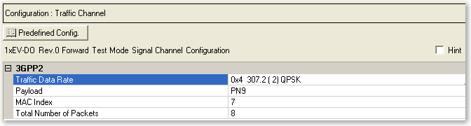
Traffic Channel
Opens a drop-down menu
of predefined channel configuration selections. Double-clicking a configuration
replaces the current configuration in the Channel Configuration window
and displays it at the top of the window.
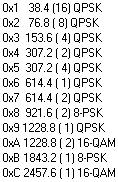
3GPP2
Traffic Data
Rate
Selections: Several
Selections
Default: 0x4 307.2 (2) QPSK
Sets the traffic channel data rate set. Each set, for example 0x4 307.2
(2) QPSK, includes the data rate control (DRC) value (0x4), data rate
(307.2 kbps), number of slots per packet (2), and modulation type (QPSK).
Payload
Selections: PN9, PN15, User Defined Bits
Default: PN9
Sets the data type (bit pattern) to be transmitted during the medium
access control (MAC) layer portion of the physical layer packet. The default
selection is PN9.
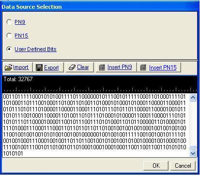
The  icon at the right of the entry box opens
the Data Source Selection dialog box.
icon at the right of the entry box opens
the Data Source Selection dialog box.
The Data Source Selection dialog box allows you to select from PN9,
PN15, or User Defined Bits.
To select from the following data types,
click the desired radio selection:
PN9
Provides a pseudo-random bit sequence containing 511 bits (29-1)
. When there are not enough bits left in the PN sequence to fill a frame,
the software repeats the data sequence. When the maximum length is reached,
it truncates any remaining data. If this is the selection, you are returned
to the Channel Setup pane.
PN15
Provides a pseudo-random bit sequence containing 32,767 bits (215-1) . When there
are not enough bits left in the PN sequence to fill a frame, the software
repeats the data sequence. When the maximum length is reached, it truncates
any remaining data. If this is the selection, you are returned to the
Channel Setup pane.
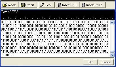
User Defined Bits
Opens the user data entry area,
which lets you customize the transmitted data.
The user data entry area contains buttons to import, export, or clear
user data along with the ability to insert PN9 or PN15 data. Optionally
you can manually insert or delete data. To manually insert data, simply
place the cursor within the data entry area or
highlight existing bits, and insert data. There are three ways to insert
data:
-
using the 1 and 0 keys
on the keyboard
-
using the Insert PN9 or
PN15 button
-
pasting data from a file or from within the current
view
(The key board shortcuts Ctrl+C and Ctrl+V work for user data entry.)
To delete data, simply place the cursor at the desired location within
the data or highlight bits, and delete the data. The key board shortcut
Ctrl+Z also deletes highlighted data.
The maximum number of bits for the user data entry area is 65,536, which
is also the maximum file size.
The expanded area has five buttons that can be used to manipulate data
for the channel.
The five buttons in the expanded area are:
Import
Loads a user-defined pattern from a selected
location. When you select this button, the Open user defined data dialog
box appears for navigating to and selecting the desired file. An imported
file automatically updates the user data entry area. The software accepts
the following file types:
The maximum file size is 65,536 bits. If the imported file is larger
than 65,536 bits, the software truncates the bits to conform to the maximum
file size.
Export
Saves the current data pattern, showing
in the user data entry area, to a file. When you select this button, a
Save user defined data dialog box appears for navigating to the location
where you can save the file. The software saves the user data as one of
the following selected file types:
Clear
Clears all data showing in the user data entry area.
Insert PN9
Inserts a fixed pattern pseudo-random bit sequence containing 511 bits
(29-1) into
the user data entry area. The software generates this fixed pattern in
accordance with the CCITT recommendation O.153. Repeated clicking of this
button adds additional PN9 sequences until the software attains the maximum
file size of 65,536 bits. The software truncates data in excess of the
maximum file size.
To edit the data pattern, insert the cursor at the desired point in
the file and click Insert PN9, or enter the information manually using
the keyboard keys 1 and 0. The software inserts the data at the cursor
position and truncates all data in excess of 65,536 bits.
Insert PN15
Inserts a fixed pattern pseudo-random bit sequence containing 32,767
bits (215-1)
into the user data entry area. The software generates this fixed pattern
in accordance with the CCITT recommendation O.153. Repeated clicking of
this button adds additional PN15 sequences until the software attains
the maximum file size of 65,536 bits. The software truncates data in excess
of the maximum file size.
To edit the data pattern, insert the cursor at the desired point in
the file and click Insert PN15, or enter the information manually using
the keyboard keys 1 and 0. The software inserts the data at the cursor
position and truncates all data in excess of 65,536 bits.
MAC Index
Range: 5 to 63
Default: 7
Sets the medium access control (MAC) index for the forward link traffic
channel.
Total Number
of Packets
Range: 1 to 16
Default: 8
Sets the number of unique physical layer packets to be transmitted over
the traffic channel.
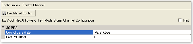
Control Channel
Opens a drop-down menu
of predefined channel configuration selections. Double-clicking a configuration
replaces the current configuration in the Channel Configuration window
and displays it at the top of the window.
3GPP2
Control
Data Rate
Selections: 38.4 or 76.8 kbps
Default: 38.4 kbps
Sets the data rate for the control channel.
Pilot PN Offset
Range: 0 to 511
Default: 0
Sets the pilot channel’s PN offset index. The PN offset of the pilot
channel indicates the cell or sector of the transmitting access network.