Real Time
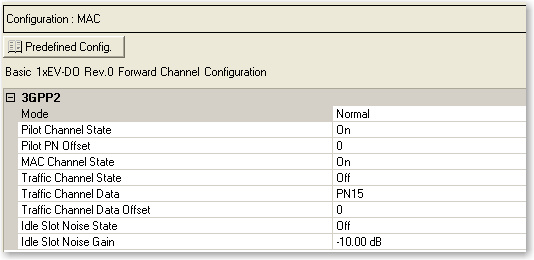
Channel Setup: Basic 1xEV-DO Rev.0 Forward
Buttons
Opens a  drop-down menu
of predefined channel configuration selections. Double-clicking a configuration
replaces the current configuration in the Channel Configuration window
and displays it at the top of the window.
drop-down menu
of predefined channel configuration selections. Double-clicking a configuration
replaces the current configuration in the Channel Configuration window
and displays it at the top of the window.
3GPP2
Mode
Selections: Normal, Continuous Pilot
Default: Normal
Sets the operating mode.
Normal - In this mode, a 1xEV-DO frame with custom channel configurations
in each of the frame's 16 timeslots can be configured. The pilot channel,
MAC channel, and traffic channel are supported in normal operating mode.
Continuous Pilot - This mode provides a fundamental test signal to be
used as a troubleshooting tool to verify basic operation of the device
under test. Instead of two pilot channel bursts occurring in each of the
frame’s 16 timeslots, the pilot channel is continuously active during
each frame timeslot, and thus over the entire 1xEV-DO frame. In this mode
of operation, the pilot channel is the only available channel type.
Pilot Channel
State
Selections: On, Off
Default: On
Is the default active channel in every frame and occurs as two distinct
bursts (in normal mode) in each timeslot of the frame.
Pilot PN
Offset
Range: 0 to 511
Default: 0
Sets the pilot channel’s PN offset index. The PN offset of the pilot
channel indicates the cell or sector of the transmitting access network.
MAC Channel
State
Selections: On, Off
Default: On
Sets the state of the medium access control (MAC) channel for the entire
frame. Any channel configuration done at the timeslot level is not valid
unless the channel is activated for use in the entire frame.
Traffic
Channel State
Selections: On, Off
Default: Off
Sets the state of the traffic channel for the entire frame. Any channel
configuration done at the timeslot level is not valid unless the channel
is activated for use in the entire frame.
Traffic
Channel Data
Selections: PN15
Default: PN9, PN15, User Defined Bits
Sets the data type (bit pattern) for the traffic channel. The traffic
channel must be activated before you can select the data type.
The traffic channel bit stream is divided into each timeslot with an
active traffic channel for the entire frame. In the case of PN sequences,
a continuous PN sequence is distributed across the timeslots with an active
traffic channel. After the last timeslot with an active traffic channel
has been filled with data, the PN sequence is truncated.
The  icon at the right of the entry box opens
the Data Source Selection dialog box.
icon at the right of the entry box opens
the Data Source Selection dialog box.
The Data Source Selection dialog box allows you to select from PN9,
PN15, or User Defined Bits.
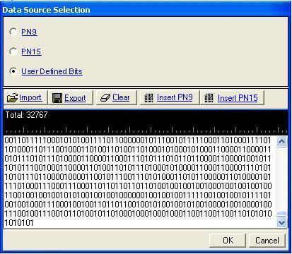
To select from the following data types, click the desired radio selection:
PN9
Provides a pseudo-random bit sequence containing 511 bits (29-1).
When there are not enough bits left in the PN sequence to fill a frame,
the software repeats the data sequence. When the maximum length is reached,
it truncates any remaining data. If this is the selection, you are returned
to the Channel Setup pane.
PN15
Provides a pseudo-random bit sequence containing 32,767 bits (215-1). When there
are not enough bits left in the PN sequence to fill a frame, the software
repeats the data sequence. When the maximum length is reached, it truncates
any remaining data. If this is the selection, you are returned to the
Channel Setup pane.
User Defined Bits
Opens the user data entry area,
which lets you customize the transmitted data.
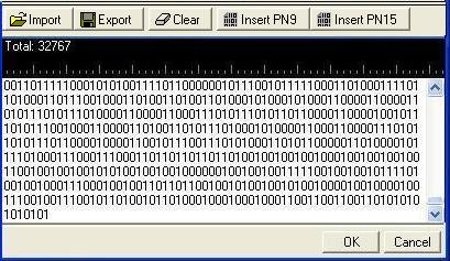
The user data entry area contains buttons to import, export, or clear
user data along with the ability to insert PN9 or PN15 data. Optionally
you can manually insert or delete data. To manually insert data, simply
place the cursor within the data entry area or
highlight existing bits, and insert data. There are three ways to insert
data:
-
using the 1 and 0 keys
on the keyboard
-
using the Insert PN9 or
PN15 button
-
pasting data from a file or from within the current
view
(The key board shortcuts Ctrl+C and Ctrl+V work for user data entry.)
To delete data, simply place the cursor at the desired location within
the data or highlight bits, and delete the data. The key board shortcut
Ctrl+Z also deletes highlighted data.
The maximum number of bits for the user data entry area is 65,536, which
is also the maximum file size.
The expanded area has five buttons that can be used to manipulate data
for the channel.
The five buttons in the expanded area are:
Import
Loads a user-defined pattern from a selected
location. When you select this button, the Open user defined data dialog
box appears for navigating to and selecting the desired file. An imported
file automatically updates the user data entry area. The software accepts
the following file types:
The maximum file size is 65,536 bits. If the imported file is larger
than 65,536 bits, the software truncates the bits to conform to the maximum
file size.
Export
Saves the current data pattern, showing
in the user data entry area, to a file. When you select this button, a
Save user defined data dialog box appears for navigating to the location
where you can save the file. The software saves the user data as one of
the following selected file types:
Clear
Clears all data showing in the user data entry area.
Insert PN9
Inserts a fixed pattern pseudo-random bit sequence containing 511 bits
(29-1) into
the user data entry area. The software generates this fixed pattern in
accordance with the CCITT recommendation O.153. Repeated clicking of this
button adds additional PN9 sequences until the software attains the maximum
file size of 65,536 bits. The software truncates data in excess of the
maximum file size.
To edit the data pattern, insert the cursor at the desired point in
the file and click Insert PN9, or enter the information manually using
the keyboard keys 1 and 0. The software inserts the data at the cursor
position and truncates all data in excess of 65,536 bits.
Insert PN15
Inserts a fixed pattern pseudo-random bit sequence containing 32,767
bits (215-1)
into the user data entry area. The software generates this fixed pattern
in accordance with the CCITT recommendation O.153. Repeated clicking of
this button adds additional PN15 sequences until the software attains
the maximum file size of 65,536 bits. The software truncates data in excess
of the maximum file size.
To edit the data pattern, insert the cursor at the desired point in
the file and click Insert PN15, or enter the information manually using
the keyboard keys 1 and 0. The software inserts the data at the cursor
position and truncates all data in excess of 65,536 bits.
Traffic
Channel Data Offset
Range: 0 to 32768
Default: 0
Sets the number of bits that the payload data is offset. For example,
if the payload data is 0110 and the offset is 2, the resulting bit stream
begins with the third bit (1), skipping over the first two (01) before
continuing to repeat the selected pattern (0110). Therefore, in this example,
the pattern would be 10011001100110... and so on.
Idle
Slot Noise State
Selections: On, Off
Default: Off
Allows an idle slot to have a controllable low level of noise, rather
than no signal, to improve the on/off ratio that must be handled by the
component. This low level of the noise is controlled by the Idle Slot
Gain parameter. During idle slot transmission, a large on/off power ratio
requires that the access network power amplifier have extremely wide dynamic
range. This is typically not the case. To address this issue, the idle
slot noise function allows the noise level during the off time of the
idle slot to be varied relative to the pilot channel. By varying the idle
slot gain, the on/off power ratio can be set as needed to meet the transmission
envelope mask requirements of the system. When the idle slot noise is
disabled, RF blanking (turning off the RF signal in certain conditions)
is automatically enabled, which results in a very large on/off power ratio
during idle slot transmission.
Idle Slot Noise
Gain
Range: -80 dB to 0 dB
Default: -10 dB
Allows the noise level during the off time of the idle slot to be varied
relative to the pilot channel. By varying the idle slot gain, the on/off
power ratio can be set as needed to meet the transmission envelope mask
requirements of the system. To set the idle slot gain, the idle slot noise
function must be enabled first.
Related Topics
Timeslots