In a CDMA waveform, high power peaks can cause intermodulation distortion, which generates spectral regrowth (a condition that interferes with signals in adjacent frequency bands). The clipping function allows you to reduce high power peaks.
To understand how clipping reduces high power peaks, it is important to know how the peaks develop as the signal is constructed. For this section, we will discuss power peaks relative to a CDMA signal.
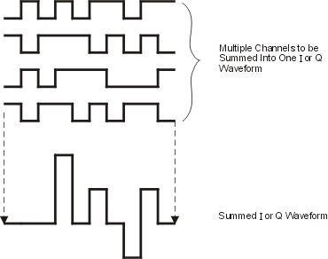
A CDMA waveform is composed of an I waveform and a Q waveform. Often, these waveforms are the summation of multiple channels (see graphic below). Whenever most or all of the individual channel waveforms simultaneously contain a bit in the same state (high or low), an unusually high power peak (negative or positive) occurs in the summed waveform. This does not happen frequently because the high and low states of the bits on these channel waveforms are random, which causes a cancelling effect.

The I and Q waveforms combine in the I/Q modulator to create an RF waveform.
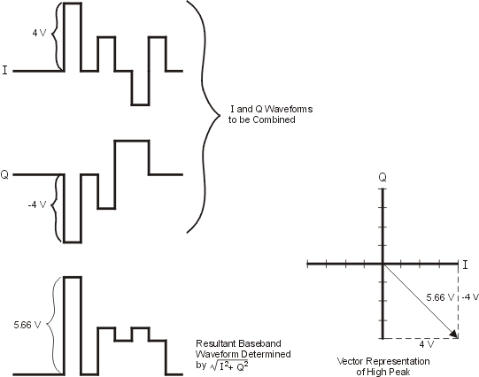
The magnitude of the RF envelope is determined by the equation  ,
where the squaring of I and Q always results in a positive value. Notice
how simultaneous positive and negative peaks in the I and Q waveforms
do not cancel each other, but combine to create an even greater peak (see
graphic below).
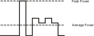
Because of the relative infrequency of high power peaks, a waveform will have a high peak-to-average power ratio (see graphic below). Because a transmitter’s power amplifier gain is set to provide a specific average power, high peaks can cause the power amplifier to move toward saturation. This causes intermodulation distortion, which generates spectral regrowth.
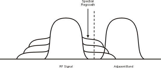
Spectral regrowth is a range of frequencies that develops on each side of the carrier (similar to sidebands) and extends into the adjacent frequency bands (see graphic below). Consequently, spectral regrowth interferes with communication in the adjacent bands. Clipping can provide a solution to this problem.
You can reduce peak-to-average power, and consequently spectral regrowth, by clipping the waveform to a selected percentage of its peak power. The Signal Studio software provides circular clipping. Though the software doesn't provide rectangular clipping, it is discussed here for comparison.
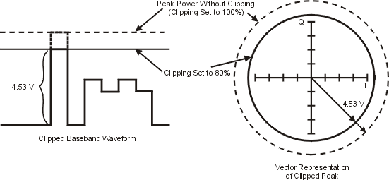
During circular clipping, clipping is applied to the combined I and Q RF waveform (|I + jQ|). Notice in the graphic below that the clipping level is constant for all phases of the vector representation and appears as a circle.
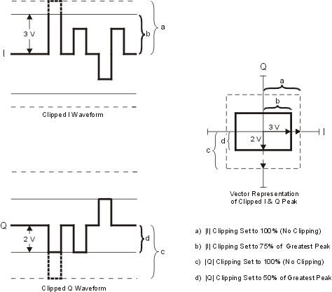
During rectangular clipping, clipping is applied to the I and Q waveforms separately (|I|, |Q|). Notice in the graphic below that the clipping level is different for I and Q; therefore, it appears as a rectangle in the vector representation. With either method, the objective is to clip the waveform to a level that effectively reduces spectral regrowth, but does not compromise the integrity of the signal.
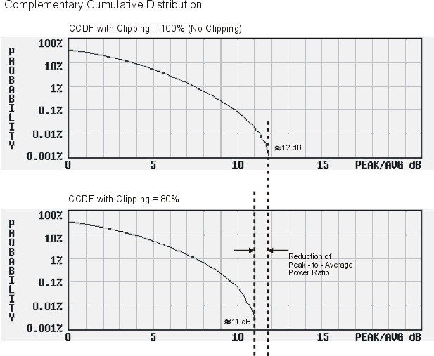
The graphic below uses two complementary cumulative distribution plots to show the reduction in peak-to-average power that occurs after applying circular clipping to an RF waveform. The lower you set the clipping value, the lower the peak power that is passed (or the more the signal is clipped). Often, the peaks can be clipped successfully without substantially interfering with the rest of the waveform. Data that might be lost in the clipping process is salvaged because of the error correction inherent in the coded systems. If you clip too much of the waveform, however, lost data is irrecoverable. You may have to try several clipping settings to find a percentage that works well.
The Signal Studio software allows you to choose whether clipping occurs prior to, or after, FIR filtering. Because clipped waveforms have abrupt discontinuities which can generate noise, you can select pre-FIR filter clipping. The FIR filter smooths any discontinuities in the clipped waveform and prevents noise. If desired, however, you can also select post-FIR filter clipping.