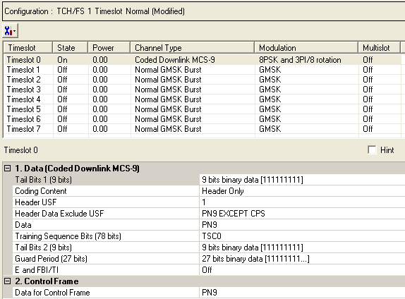
MCS-5, MCS-6, MCS-7, MCS-8, and MCS-9 are coded DL Packet Data Transport Channels (PDTCH) that are available with Option QFP.To open the Data node, click Data in the tree view. Use the Data window to define the bits in the bursts. The cells displayed in the Data node are determined by the Channel Type, as defined in the Timeslot window, for the selected timeslot.
The timeslots shown below are set to show some of the available timeslot (channel) types, not to show a typical test configuration.
Figure: Coded MCS-5, MCS-6, MCS-7, MCS-8, and MCS-9 Downlink Data Nodes

|
1. Data (Normal GMSK Burst) |
|---|
|
2. Control Frame |
Click  to display a drop-down menu in which you can copy a timeslot configuration
from one timeslot to another.
Use the Data window to define the bits in the bursts. The cells displayed in the Data section are determined by the burst type (Timeslot Type) for the selected timeslot as defined in the Timeslots window. In the window shown above, Timeslot 0 is set up for a data cell with a Modulation and Coding Scheme 9 (MCS-9) downlink burst.
Default: X"1FF"
Click the Details Button  in this cell to open the
 ![]() Data Source Selection
window. Enter 9 bits to use in the first of the two tail bit segments
of the burst.
Data Source Selection
window. Enter 9 bits to use in the first of the two tail bit segments
of the burst.
Choice: Header Only | Header and Data
Default: Header Only
The Header Only selection is used for EGPRS operation, the waveform must be able to apply the PN data bits directly to individual bursts, without coding and interleaving. But, the test waveform must still perform the required coding/interleaving/signaling for the USF and header bits.
The Header and Data is used to follow standard, which requires both the header bits and data bits to be coded and interleaved.
Range: 0 to 7
Default: 1
Double-click or use the drop-down menu to set the 3-bit Header USF (Uplink Status Flag) value.
Choice: PN9 EXCEPT CPS| PN9 | PN15 | User Defined Bits
Default: PN9 EXCEPT CPS
Double-click or use the![]() drop-downmenu to set the
drop-downmenu to set the ![]() Header Data Exclude USF.
Header Data Exclude USF.
Choice: PN9 |PN15 | User Defined Bits
Default: PN9
Click the Details button  in this cell to open the
 ![]() Data Source
Selection
window.
Data Source
Selection
window.
Select an encoded , or . The selected data is coded continuously across the RLC data block per the 3GPP standards. An independent version of the selected data is coded across the unused RLC/MAC header fields.
To perform a receiver test with a continuous PN sequence, select .
Choices: TSC0 to TSC7
Default: TSCO
Click the Details button  in this cell to open the
 ![]() Data Source Selection
window.
Data Source Selection
window.
Select to or to use for the training sequence bits.
If you manually change a timeslot (channel type), the training sequence for that timeslot resets to provided that the training sequence was not previously changed for the new channel type.
The training sequences selections are defined as follows:
|
TSC0 |
3F3F 9E49 FFF3 FF3F 9E49 |
|
TSC1 |
3F3C 9E49 E493 EE3C 9E49 |
|
TSC2 |
39FF F24F 24F3 F9FF F24F |
|
TSC3 |
39FF 924F 279F F9FF 924F |
|
TSC4 |
3FE4 F3C9 3F9F FFE4 F3C9 |
|
TSC5 |
39FC 93CF 27FF F9FC 93CF |
|
TSC6 |
0F3F 9249 E4FF CF3F 9249 |
|
TSC7 |
093C 927F E7F3 C93C 927F |
Select to define ![]() custom training sequence
bits.
custom training sequence
bits.
Default: X"1FF"
Click the Details button  in this cell to open the Data Source Selection.
![]() Enter 9-bits
to use in the second of the two tail bit segments of the burst.
Enter 9-bits
to use in the second of the two tail bit segments of the burst.
Default: X"7FFFFFF"
Guard period bits are set by the software. You cannot edit this cell.
Choice: On | Off
Default: Off
Double-click or use the drop-down menu to set the
state. Sets the Extension (E) bit and either the Final Block Indicator
(FBI) bit in the downlink or the TTLI Indicator (TI) bit in the uplink
(See ![]() E and FBI/TI data block structure).
E and FBI/TI data block structure).
Choice: PN9 |PN15 | User Defined Bits
Default: PN9
Set the data for the control frame within a multiframe
setup. Click the Details button  in this cell to open the
 ![]() Data Source Selection
window.
Data Source Selection
window.
Select ,
or . Select to ![]() create
a data string.
create
a data string.
If the Multiframe type parameter at the Carrier n node is set to , the parameter, while appearing as active, has no effect since there is no control frame.