Fading
1. Fader Settings
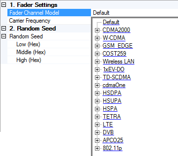
Fader Channel Model
Use the drop-down menu to select a default or standards-based fading model. The standard models cover SISO propagation environments that allow you to test whether your device meets the performance requirements as defined by the respective standard. The software automatically populates the path configurations for the selected standard model.
[:SOURce]:FSIMulator[1]:FADer[1]:STANdard:SCModel DEFault|<SISO_Channel_Model_Name>
[:SOURce]:FSIMulator[1]:FADer[1]:STANdard:SCModel?
Click the links below to see the SCPI syntax for executing the various SISO fading models. The syntax for each fading model appears in the exact same order (top to bottom) as the software's GUI, allowing you to compare and confirm you have the correct syntax for the fading model you want to execute.
 cdma2000
Carrier Frequency
Default: 1.0 GHz
Range: 1 to 44 GHz
Sets the carrier frequency to be used for Doppler effects in the fading simulations. The Carrier Frequency setting is coupled with the Frequency setting under the Instrument node. Also if you change the Carrier Frequency value, the Doppler Frequency or the Vehicle Speed settings under the Fader Path node will be changed.
When using SCPI, the instrument frequency and carrier frequency settings are not coupled, as they are when using the GUI. Therefore you must send separate commands to ensure both are the same. Also, you must repeat these commands each time you set the fader channel model because some models change the carrier frequency, but not the instrument frequency.
Example:
[:SOURce]:FSIMulator[1]:FADer[1]:STANdard:SCModel IEEE11PRLOS (sets fader channel model)
[:SOURce]:FSIMulator[1]:FADer[1]:FREQuency 5.86GHz (sets carrier frequency)
:FREQ 5.86GHz (sets instrument frequency)
[:SOURce]:FSIMulator[1]:FADer[1]:FREQuency <val>
[:SOURce]:FSIMulator[1]:FADer[1]:FREQuency?
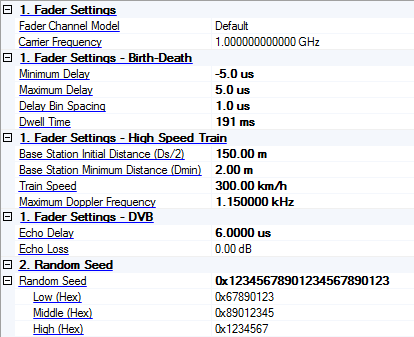
1. Fader Settings - Birth-Death
These parameters apply to the following fading models only. In addition, for the associated SCPI command to be valid, one of these fading models must be executed first. See Fader Channel Model.
-
W-CDMA/Base Station
-
W-CDMA/Mobile Station
Minimum Delay
Range: -100 ns to -25 us
Default: -5 us
Minimum Delay sets the minimum birth-death path delay when you select a Birth-Death delay profile.
[:SOURce]:FSIMulator[1]:FADer[1]:STANdard:WCDMa:MINDelay <val>
[:SOURce]:FSIMulator[1]:FADer[1]:STANdard:WCDMa:MINDelay?
Maximum Delay
Range: 100 ns to 25 us
Default: 5 us
Maximum Delay sets the maximum birth-death path delay when you select a Birth-Death delay profile.
[:SOURce]:FSIMulator[1]:FADer[1]:STANdard:WCDMa:MAXDelay <val>
[:SOURce]:FSIMulator[1]:FADer[1]:STANdard:WCDMa:MAXDelay?
Delay Bin Spacing
Range: 100 ns to 5 us
Default: 1 us
Delay Bin Spacing sets the size of the radom hops when you select a Birth-Death delay profile.
[:SOURce]:FSIMulator[1]:FADer[1]:STANdard:WCDMa:DBSPacing <val>
[:SOURce]:FSIMulator[1]:FADer[1]:STANdard:WCDMa:DBSPacing?
Dwell Time
Range: 0.1 s to 1.0 s
Default: 191 ms
Dwell Time sets the duration of each birth-death state when you select a Birth-Death delay profile.
[:SOURce]:FSIMulator[1]:FADer[1]:STANdard:WCDMa:DTIMe <val>
[:SOURce]:FSIMulator[1]:FADer[1]:STANdard:WCDMa:DTIMe?
1. Fader Settings - High Speed Train
These parameters apply to the following fading models only. In addition, for the associated SCPI command to be valid, one of these fading models must be executed first. See Fader Channel Model.
-
W-CDMA/High Speed Train/Tunnel
-
W-CDMA/High Speed Train/Open Space
-
LTE/High Speed Train/Open Space
-
LTE/High Speed Train/Tunnel
Base Station Initial Distance (Ds/2)
Range: 5 m to 50 km
Default: Varies by channel model
Sets the initial distance (Ds/2) that the mobile must travel before passing the base station when you select a high speed train profile.
[:SOURce]:FSIMulator[1]:FADer[1]:STANdard:WCDMa:HSTrain:BSIDistance <val>
[:SOURce]:FSIMulator[1]:FADer[1]:STANdard:WCDMa:HSTrain:BSIDistance?
[:SOURce]:FSIMulator[1]:FADer[1]:STANdard:LTE:HSTrain:BSIDistance <val>
[:SOURce]:FSIMulator[1]:FADer[1]:STANdard:LTE:HSTrain:BSIDistance?
Base Station Minimum Distance (Dmin)
Range: 1 m to 1 km
Default: Varies by channel model
Sets the minimum distance from the mobile to the base station (BS-Railway track distance) when you select a high speed train profile.
[:SOURce]:FSIMulator[1]:FADer[1]:STANdard:WCDMa:HSTrain:BSMDistance <val>
[:SOURce]:FSIMulator[1]:FADer[1]:STANdard:WCDMa:HSTrain:BSMDistance?
[:SOURce]:FSIMulator[1]:FADer[1]:STANdard:LTE:HSTrain:BSMDistance <val>
[:SOURce]:FSIMulator[1]:FADer[1]:STANdard:LTE:HSTrain:BSMDistance?
Train Speed
Range: 0 to 1000 km/h
Default: Varies by channel model
Sets the speed of the train when you select a high speed train profile.
[:SOURce]:FSIMulator[1]:FADer[1]:STANdard:WCDMa:HSTrain:TSPeed <val>
[:SOURce]:FSIMulator[1]:FADer[1]:STANDard:WCDMa:HSTrain:TSPeed?
[:SOURce]:FSIMulator[1]:FADer[1]:STANdard:LTE:HSTrain:TSPeed <val>
[:SOURce]:FSIMulator[1]:FADer[1]:STANDard:LTE:HSTrain:TSPeed?
Maximum Doppler Frequency
Range: 0 to 1.6 kHz
Default: Varies by channel model
Sets the maximum Doppler frequency for the fading simulation when you select a high speed train profile.
[:SOURce]:FSIMulator[1]:FADer[1]:STANdard:WCDMa:HSTrain:MDFRequency <val>
[:SOURce]:FSIMulator[1]:FADer[1]:STANdard:WCDMa:HSTrain:MDFRequency?
[:SOURce]:FSIMulator[1]:FADer[1]:STANdard:LTE:HSTrain:MDFRequency <val>
[:SOURce]:FSIMulator[1]:FADer[1]:STANdard:LTE:HSTrain:MDFRequency?
1. Fader Settings - DVB
These parameters apply to the following fading models only. In addition, for the associated SCPI command to be valid, one of these fading models must be executed first. See Fader Channel Model.
-
DVB/DVB-H/Mobile SFN/Weak Long Echo
-
DVB/DVB-H/Mobile SFN/Strong Long Echo
-
DVB/DVB-H/Mobile SFN/Strong Short Echo
Echo Delay
Range: 0 to 1 ms
Default: Varies by channel model
Sets the additional delay for DVB fading paths 7-12 that are part of the echo.
[:SOURce]:FSIMulator[1]:FADer[1]:STANdard:EDELay <val>
[:SOURce]:FSIMulator[1]:FADer[1]:STANdard:EDELay?
Echo Loss
Range: 0 to 20 dB
Default: Varies by channel model
Sets the additional loss for DVB fading path 7-12 that are part of the echo.
[:SOURce]:FSIMulator[1]:FADer[1]:STANdard:ELOSs <val>
[:SOURce]:FSIMulator[1]:FADer[1]:STANdard:ELOSs?
2. Random Seed
Random Seed
Range: 0 to 2^89 – 1
Sets the random number generation seed of the fading channel. If it is set to zero, the generated fading will be different for each playback to provide randomness for each test. To reproduce the same fading environment for the same configuration as the last time it was played, use the same seed value (other than 0) each time.
You can enter the entire 89-bit sequence directly into the random seed cell or use the high, medium, and low cells to designate the number in three segments for easier data entry.
[:SOURce]:FSIMulator[1]:SEED "<val>"
Low (Hex)
Specifies the lowest bits (0x0 to 0xFFFFFFFF).
Middle (Hex)
Specifies the middle bits (0x0 to 0xFFFFFFFF).
High (Hex)
Specifies the upper bits (0x0 to 0x1FFFFFF).