This topic describes the parameters in the Fader Path configuration table.
Restores the standard path settings in the active fader path pane for the selected channel model. (Applying this button restores all Fader Paths to their default settings.) It also restores the default settings for the carrier frequency and the random seed.

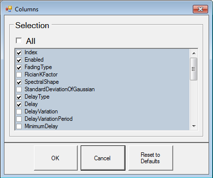
 Column Headings for path parameters that can be displayed. Click
each parameter to show or hide the visibility of that column.
Column Headings for path parameters that can be displayed. Click
each parameter to show or hide the visibility of that column.
Displays the channel bandwidth depending on the number of enabled.
|
Paths |
Channel Bandwidth |
|---|---|
|
0-6 |
160 MHz |
|
7-12 |
80 MHz |
|
13-24 |
40 MHz |
You can use and on your keyboard to change the value of certain parameters, for example Delay. Holding down or with the Page Up/Down keys multiplies the step by a factor of 10 and 100, respectively.
|
Column Headings: |
|
|---|---|
|
|
|
Values: 1 to 24
Displays the row number of the path.
Choices: On, Off
Default: Path 1: On, Paths 2-24: Off
Sets the state for a specific path when you select or clear the check box.
[:SOURce]:FSIMulator[1]:FADer[1]:PATH[1]|2|3|4|5|6|7|8|9|10|11|12|13|14|15|16|17|18|19|20|21|22|23|24:ENABle 1|0|ON|OFF
[:SOURce]:FSIMulator[1]:FADer[1]:PATH[1]|2|3|4|5|6|7|8|9|10|11|12|13|14|15|16|17|18|19|20|21|22|23|24:ENABle?
Choices: Static, Pure Doppler, Rayleigh, Rician, Suzuki
Selects the type of amplitude distribution to be applied in the fader simulation.
Static
Required for 802.11p channel models. Vehicle Speed and Doppler Frequency values are read-only and set to 0.
Pure Doppler
Simulates pure Doppler fading by using non-zero Doppler frequencies and LOS AOA not equal to 90 or 270 degrees, or constant phase fading with either zero Doppler frequency and/or LOS AOA set to 90 or 270 degrees.
Rayleigh
Simulates the rapid amplitude fluctuations where there is no direct ray component (LOS) in small scale fading environments to model local scattering near the receiver.
Rician
Adds a line-of-sight component (LOS) to the Rayleigh model. This model is often used to simulate a rural environment and small office spaces.
Suzuki
Superimposes the log normal distribution onto the Rayleigh distribution. This is often used to simulate the effects of a dense urban environment with the average received power level fluctuating slowly due to shadowing effects. If you select Suzuki as a fading type, the Log Normal parameter is also enabled.
[:SOURce]:FSIMulator[1]:FADer[1]:PATH[1]|2|3|4|5|6|7|8|9|10|11|12|13|14|15|16|17|18|19|20|21|22|23|24:FTYPe RAYLeigh|RICian|SUZuki|PDOPpler|STATic
[:SOURce]:FSIMulator[1]:FADer[1]:PATH[1]|2|3|4|5|6|7|8|9|10|11|12|13|14|15|16|17|18|19|20|21|22|23|24:FTYPe?
Range: –84 to 84 dB
Default: 0 dB
Sets the K factor when using the Rician fading type. The K factor is the power ratio between the direct ray and the Rayleigh component of the fade. A K factor of 6 indicates that the direct ray is 6 dB stronger than the Rayleigh component.
[:SOURce]:FSIMulator[1]:FADer[1]:PATH[1]|2|3|4|5|6|7|8|9|10|11|12|13|14|15|16|17|18|19|20|21|22|23|24:RKFactor <val>
[:SOURce]:FSIMulator[1]:FADer[1]:PATH[1]|2|3|4|5|6|7|8|9|10|11|12|13|14|15|16|17|18|19|20|21|22|23|24:RKFactor?
Choices: Classical 6dB, Classical 3dB, Flat, Rounded, Gaussian, Jakes Classical, Jakes Rounded, Half Bathtub, Jakes Half Bathtub
Selects the power spectral shape of the Doppler spreading applied to the signal. The firmware uses two different methods to simulate various fading scenarios: filtered noise and Jakes method. When using Jakes method, the firmware approximates the Rayleigh distribution using a finite number of rays arriving at a receiver from all directions whereas the filtered noise method simulates an infinite number of rays. The firmware does not support mixing Jakes method and filtered noise method in the same simulation.
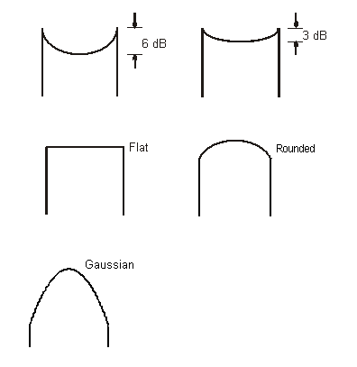
Classical 6 dB
Represents outdoor vehicular fading environments with fixed reflectors (recommended by most standards).
Classical 3 dB
Represents outdoor vehicular fading environments with fixed reflectors (optional limit) .
Flat
Represents indoor fading environments with fixed reflectors.
Rounded
Represents indoor or outdoor fading environments for fixed stations with moving reflectors.
Gaussian
Represents slow moving hand-held reception.
Jakes Classical
Represents vehicular fading environments with fixed reflectors (corresponds to the 3 dB and 6 dB shape using the filtered noise method).
Jakes Rounded
Represents indoor or outdoor fading environments for fixed stations with moving reflectors (corresponds to the rounded shape using the filtered noise method).
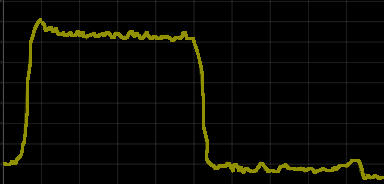
Half Bathtub
Represents a particular vehicular fading environment. For example, cars and trucks reflecting and stretching signals as they pass through an urban intersection. It is half of the Classical 6 dB spectral shape (view image).
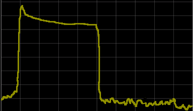
Jakes Half Bathtub
Represents a particular vehicular fading environment. For example, cars and trucks reflecting and stretching signals as they pass through an urban intersection. It is half of the Jakes Classical spectral shape (view image).
[:SOURce]:FSIMulator[1]:FADer[1]:PATH[1]|2|3|4|5|6|7|8|9|10|11|12|13|14|15|16|17|18|19|20|21|22|23|24:SSHape 3DB|C6DB|FLAT|ROUNded|JCLassical|JROunded|GAUSsian|HBAThtub|JHBathtub
[:SOURce]:FSIMulator[1]:FADer[1]:PATH[1]|2|3|4|5|6|7|8|9|10|11|12|13|14|15|16|17|18|19|20|21|22|23|24:SSHape?
This column only appears when the Spectral Shape for one or more paths is set to Gaussian.
Range: 0.05 to 0.2
Default: 0.1
Sets the path's standard deviation of the Gaussian distribution with a minimum resolution of 0.01. To set the deviation, first set the path's Spectral Shape to Gaussian. After setting the Spectral Shape to Gaussian, the Std Deviation of Gaussian column appears. Once visible, this column shows a value for each path whether Gaussian is the spectral shape. However the value is valid only while Gaussian is a path's spectral shape.
[:SOURce]:FSIMulator[1]:FADer[1]:PATH[1]|2|3|4|5|6|7|8|9|10|11|12|13|14|15|16|17|18|19|20|21|22|23|24:SDGaussian <val>
[:SOURce]:FSIMulator[1]:FADer[1]:PATH[1]|2|3|4|5|6|7|8|9|10|11|12|13|14|15|16|17|18|19|20|21|22|23|24:SDGaussian?
Choices: Fixed, Moving
Selects whether the propagation for the selected path is either fixed or moving. Fixed delay allows you to set a constant path delay. Moving delay varies the path delay over time depending on the path's Min Delay, Max Delay and Rate of Osc. settings.
[:SOURce]:FSIMulator[1]:FADer[1]:PATH[1]|2|3|4|5|6|7|8|9|10|11|12|13|14|15|16|17|18|19|20|21|22|23|24:DELay:TYPE FIXed|MOVing
[:SOURce]:FSIMulator[1]:FADer[1]:PATH[1]|2|3|4|5|6|7|8|9|10|11|12|13|14|15|16|17|18|19|20|21|22|23|24:DELay:TYPE?
Range: 0 to 2 ms
Default: 0 ns
Sets the relative delay of each path. This value is added to the inherent latency of the fading hardware.
It should be noted that if multiple paths are enabled having LOS components at the same path delay and Doppler frequency shift, the power level will be incorrect. This is because the firmware assumes that each path is independent. However, in this case, the paths are not independent and the power level will not be normalized to unity. In most cases, only one LOS component is present and even if multiple LOS components are specified, they will normally be at different path delays. The assumption holds as long as the path delay values are sufficiently spaced such that the cross-correlation between delayed paths is very small (i.e. the auto correlation function of the waveform for the LOS path delay differences is negligible).
[:SOURce]:FSIMulator[1]:FADer[1]:PATH[1]|2|3|4|5|6|7|8|9|10|11|12|13|14|15|16|17|18|19|20|21|22|23|24:DELay <val>
[:SOURce]:FSIMulator[1]:FADer[1]:PATH[1]|2|3|4|5|6|7|8|9|10|11|12|13|14|15|16|17|18|19|20|21|22|23|24:DELay?
Range: varies, depending on Max Delay setting
Default: 0 µs
Sets the minimum path delay when the Delay Type is set to Moving.
[:SOURce]:FSIMulator[1]:FADer[1]:PATH[1]|2|3|4|5|6|7|8|9|10|11|12|13|14|15|16|17|18|19|20|21|22|23|24:MINDelay <val>
[:SOURce]:FSIMulator[1]:FADer[1]:PATH[1]|2|3|4|5|6|7|8|9|10|11|12|13|14|15|16|17|18|19|20|21|22|23|24:MINDelay?
Range: varies, depending on Min Delay setting
Default: 0 µs
Sets the maximum path delay when the Delay Type is set to Moving.
[:SOURce]:FSIMulator[1]:FADer[1]:PATH[1]|2|3|4|5|6|7|8|9|10|11|12|13|14|15|16|17|18|19|20|21|22|23|24:MAXDelay <val>
[:SOURce]:FSIMulator[1]:FADer[1]:PATH[1]|2|3|4|5|6|7|8|9|10|11|12|13|14|15|16|17|18|19|20|21|22|23|24:MAXDelay?
Range: 0 to 50 rad/s
Default: 0.40 rad/s
Sets the rate at which the delay shifts between the Min Delay and Max Delay values.
[:SOURce]:FSIMulator[1]:FADer[1]:PATH[1]|2|3|4|5|6|7|8|9|10|11|12|13|14|15|16|17|18|19|20|21|22|23|24:ROSCillation <val>
[:SOURce]:FSIMulator[1]:FADer[1]:PATH[1]|2|3|4|5|6|7|8|9|10|11|12|13|14|15|16|17|18|19|20|21|22|23|24:ROSCillation?
Range: 0 to 50 µs
Default: 5 µs
Sets the amount of time by which the delay can vary.
[:SOURce]:FSIMulator[1]:FADer[1]:PATH[1]|2|3|4|5|6|7|8|9|10|11|12|13|14|15|16|17|18|19|20|21|22|23|24:DVARiation <val>
[:SOURce]:FSIMulator[1]:FADer[1]:PATH[1]|2|3|4|5|6|7|8|9|10|11|12|13|14|15|16|17|18|19|20|21|22|23|24:DVARiation?
Range: 1 to 1000
Default: 157.08
Sets the period of time in seconds.
[:SOURce]:FSIMulator[1]:FADer[1]2|3|4|5|6|7|8:PATH[1]|2|3|4|5|6|7|8|9|10|11|12|13|14|15|16|17|18|19|20|21|22|23|24:DVPeriod <val>
[:SOURce]:FSIMulator[1]:FADer[1]2|3|4|5|6|7|8:PATH[1]|2|3|4|5|6|7|8|9|10|11|12|13|14|15|16|17|18|19|20|21|22|23|24:DVPeriod?
Range: 0 to 84 dB
Default: 0
Sets the amount of relative path loss. This setting assumes that the cross-correlation between paths is very small. If not, the power may be incorrect.
Path loss or power attenuation occurs with reflected signals as a result of the added distance they travel compared to the line-of-sight signal. Other factors may also contribute to signal power attenuation, such as reflected surface characteristics.
[:SOURce]:FSIMulator[1]:FADer[1]:PATH[1]|2|3|4|5|6|7|8|9|10|11|12|13|14|15|16|17|18|19|20|21|22|23|24:LOSS <val>
[:SOURce]:FSIMulator[1]:FADer[1]:PATH[1]|2|3|4|5|6|7|8|9|10|11|12|13|14|15|16|17|18|19|20|21|22|23|24:LOSS?
Range: Varies depending on the maximum Doppler frequency and the carrier frequency
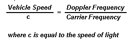
Sets the speed of the vehicle in kilometers per hour. If you change the vehicle speed, the Doppler frequency will be adjusted according to the current carrier frequency. The vehicle speed resolution will decrease as the number of paths is increased or the fader bandwidth is decreased and is limited by the maximum allowable Doppler frequency. Negative speed values only apply when the Spectral Shape is set to Half Bathtub.
[:SOURce]:FSIMulator[1]:FADer[1]:PATH[1]|2|3|4|5|6|7|8|9|10|11|12|13|14|15|16|17|18|19|20|21|22|23|24:VSPeed <val>
[:SOURce]:FSIMulator[1]:FADer[1]:PATH[1]|2|3|4|5|6|7|8|9|10|11|12|13|14|15|16|17|18|19|20|21|22|23|24:VSPeed?
Range: -6400 Hz to 6400 Hz
Default: 0
Sets the maximum Doppler frequency. The width of the Doppler spread is twice the Doppler frequency. If you change the Doppler frequency, the vehicle speed will be adjusted accordingly. Negative frequency values only apply when the Spectral Shape is set to Half Bathtub.
[:SOURce]:FSIMulator[1]:FADer[1]:PATH[1]|2|3|4|5|6|7|8|9|10|11|12|13|14|15|16|17|18|19|20|21|22|23|24:DFRequency <val>
[:SOURce]:FSIMulator[1]:FADer[1]:PATH[1]|2|3|4|5|6|7|8|9|10|11|12|13|14|15|16|17|18|19|20|21|22|23|24:DFRequency?
Choices: Doppler Frequency, Vehicle Speed
Selects whether Doppler Frequency or Vehicle Speed is coupled to the Carrier Frequency under the Fading node in the tree view. The carrier frequency coupling applies to each path individually. However, for filtered noise spectral shapes, the carrier frequency coupling must be the same for all paths.
Doppler Frequency
With this choice, the doppler frequency will be adjusted when you change the carrier frequency.
Vehicle Speed
With this choice, the vehicle speed will be adjusted when you change the carrier frequency.
[:SOURce]:FSIMulator[1]:FADer[1]:PATH[1]|2|3|4|5|6|7|8|9|10|11|12|13|14|15|16|17|18|19|20|21|22|23|24:CFCoupling DFR|VSP
[:SOURce]:FSIMulator[1]:FADer[1]:PATH[1]|2|3|4|5|6|7|8|9|10|11|12|13|14|15|16|17|18|19|20|21|22|23|24:CFCoupling?
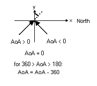
Range: –360 to 360 degrees
Default: 0
Specifies the mean of the angle of
arrival
(in degrees) of the signal for the selected path. The angle of arrival
is defined with reference to an xy (ground/antenna) plane where the x-axis
points to the geographical north and the y-axis is parallel to the ground.
[:SOURce]:FSIMulator[1]:FADer[1]:PATH[1]|2|3|4|5|6|7|8|9|10|11|12|13|14|15|16|17|18|19|20|21|22|23|24:AOA <val>
[:SOURce]:FSIMulator[1]:FADer[1]:PATH[1]|2|3|4|5|6|7|8|9|10|11|12|13|14|15|16|17|18|19|20|21|22|23|24:AOA?
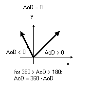
Range: –360 to 360 degrees
Default: 0
Specifies the mean of the angle of
departure
(in degrees) of the signal for the selected path. The angle of departure
is defined with reference to an xy plane (ground/antenna) plane where
the x-axis points to the geographical north and the y-axis is parallel
to the ground.
[:SOURce]:FSIMulator[1]:FADer[1]:PATH[1]|2|3|4|5|6|7|8|9|10|11|12|13|14|15|16|17|18|19|20|21|22|23|24:AOD <val>
[:SOURce]:FSIMulator[1]:FADer[1]:PATH[1]|2|3|4|5|6|7|8|9|10|11|12|13|14|15|16|17|18|19|20|21|22|23|24:AOD?
Range: 0.01 to 180 degrees
Default: 0.01
Specifies the azimuth spread of the angle of arrival at the antenna arrays of the receiver. The azimuth spread characterizes the degree of dispersion of the non-LOS signals due to multipath from a large number of local reflectors. The azimuth spread impacts the power azimuth spectrum and the correlation characteristics across the elements of the antenna array.
[:SOURce]:FSIMulator[1]:FADer[1]:PATH[1]|2|3|4|5|6|7|8|9|10|11|12|13|14|15|16|17|18|19|20|21|22|23|24:ASAOA <val>
[:SOURce]:FSIMulator[1]:FADer[1]:PATH[1]|2|3|4|5|6|7|8|9|10|11|12|13|14|15|16|17|18|19|20|21|22|23|24:ASAOA?
Range: 0.01 to 180 degrees
Default: 0.01
Specifies the azimuth (angular) spread of the angle of departure at the antenna arrays of the transmitter. The azimuth spread characterizes the degree of dispersion of the non-LOS signals due to a large number of local reflectors. The angular spread impacts the power azimuth spectrum and the correlation characteristics across the elements of the antenna array.
[:SOURce]:FSIMulator[1]:FADer[1]:PATH[1]|2|3|4|5|6|7|8|9|10|11|12|13|14|15|16|17|18|19|20|21|22|23|24:ASAOD <val>
[:SOURce]:FSIMulator[1]:FADer[1]:PATH[1]|2|3|4|5|6|7|8|9|10|11|12|13|14|15|16|17|18|19|20|21|22|23|24:ASAOD?
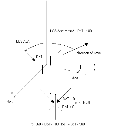
Range: 0 to 180 degrees
Default: 0
Specifies the line-of-sight
angle of arrival.
The firmware calculates the LOS Doppler shift using the LOS AoA as the
angle between the LOS component and the direction of travel.
The line-of-sight angle is defined with reference to an xy (ground/antenna)
plane where the x-axis points to the geographical north and the y-axis
is parallel to the ground.
[:SOURce]:FSIMulator[1]:FADer[1]:PATH[1]|2|3|4|5|6|7|8|9|10|11|12|13|14|15|16|17|18|19|20|21|22|23|24:LAOA <val>
[:SOURce]:FSIMulator[1]:FADer[1]:PATH[1]|2|3|4|5|6|7|8|9|10|11|12|13|14|15|16|17|18|19|20|21|22|23|24:LAOA?
Range: –360 to 360 degrees
Default: 0 degrees
The presence of a direct ray is determined by the absence of fading on that path (e.g., a Ricean direct ray, or a pure Doppler path, or a Rayleigh path with Doppler = 0). The direct ray usually falls outside the cluster PAS; therefore the angle of arrival is usually different than the cluster AoA.
[:SOURce]:FSIMulator[1]:FADer[1]: PATH[1]|2|3|4|5|6|7|8|9|10|11|12|13|14|15|16|17|18|19|20|21|22|23|24:DRAOA <val>
[:SOURce]:FSIMulator[1]:FADer[1]: PATH[1]|2|3|4|5|6|7|8|9|10|11|12|13|14|15|16|17|18|19|20|21|22|23|24:DRAOA?
Range: –360 to 360 degrees
Default: 0 degrees
The presence of a direct ray is determined by the absence of fading on that path (e.g., a Ricean direct ray, or a pure Doppler path, or a Rayleigh path with Doppler = 0). The direct ray usually falls outside the cluster PAS; therefore the angle of departure is usually different than the cluster AoD.
[:SOURce]:FSIMulator[1]:FADer[1]: PATH[1]|2|3|4|5|6|7|8|9|10|11|12|13|14|15|16|17|18|19|20|21|22|23|24:DRAOD <val>
[:SOURce]:FSIMulator[1]:FADer[1]: PATH[1]|2|3|4|5|6|7|8|9|10|11|12|13|14|15|16|17|18|19|20|21|22|23|24:DRAOD?
Range: –30 to 0 dBm
Default:–8.00 dBm
This parameter sets the power ratio between the signal received at a reference antenna oriented to match the polarization of the primary test antenna, and the power received by the same reference antenna in the same orientation, when excited by the cross polarized test antenna.
[:SOURce]:FSIMulator[1]:FADer[1]:PATH[1]|2|3|4|5|6|7|8|9|10|11|12|13|14|15|16|17|18|19|20|21|22|23|24:XPRatio <val>
[:SOURce]:FSIMulator[1]:FADer[1]:PATH[1]|2|3|4|5|6|7|8|9|10|11|12|13|14|15|16|17|18|19|20|21|22|23|24:XPRatio?
Range: 0 to 360 degrees
Default: 0 degrees
Sets the RF phase shift for the LOS component in addition to the implicit phase shift due to path delay. This is useful when the direct components, such as direct ray signals, have exactly the same frequency (and therefore, the same phase). In that case, if two equal-amplitude paths have the same delay and phase shift, the power of those two paths summed together is 3 dB higher than the power of two uncorrelated paths summed together or, equivalently, their sum is 6 dB greater than the power of each path individually. If the two paths are 180 degrees out of phase, their sum is zero.
Phase shift includes the effect of path delay. For example, if the RF frequency is 100 MHz, the duration of each 360-degree RF cycle is 10 ns (1/100 MHz). If path delay is 5 ns and the phase shift is set to zero, the actual phase shift would be 180 degrees.
[:SOURce]:FSIMulator[1]:FADer[1]:PATH[1]|2|3|4|5|6|7|8|9|10|11|12|13|14|15|16|17|18|19|20|21|22|23|24:PSHift <val>
[:SOURce]:FSIMulator[1]:FADer[1]:PATH[1]|2|3|4|5|6|7|8|9|10|11|12|13|14|15|16|17|18|19|20|21|22|23|24:PSHift?
Range: –1600 Hz to 1600 Hz
Default: 0 Hz
Sets the path's frequency offset with a minimum resolution of 0.01 Hz. Each path can have a different frequency offset. For a path, the absolute value of the frequency offset plus the Doppler frequency value must not exceed 1600 Hz.
[:SOURce]:FSIMulator[1]:FADer[1]:PATH[1]|2|3|4|5|6|7|8|9|10|11|12|13|14|15|16|17|18|19|20|21|22|23|24:FOFFset <val>
[:SOURce]:FSIMulator[1]:FADer[1]:PATH[1]|2|3|4|5|6|7|8|9|10|11|12|13|14|15|16|17|18|19|20|21|22|23|24:FOFFset?
Selects whether to use a log normal distribution of the mean signal power. Log Normal fading, also called "slow fading", simulates the slow changes in signal level due to shadowing by hills or other objects. This is in addition to the currently selected fading type. Selecting Log Normal activates the standard deviation parameters and the decorrelation length. If you select Suzuki as a fading type, the Log Normal parameter is also enabled.
[:SOURce]:FSIMulator[1]:FADer[1]:PATH[1]|2|3|4|5|6|7|8|9|10|11|12|13|14|15|16|17|18|19|20|21|22|23|24:LOGNormal On|OFF|1|0
[:SOURce]:FSIMulator[1]:FADer[1]:PATH[1]|2|3|4|5|6|7|8|9|10|11|12|13|14|15|16|17|18|19|20|21|22|23|24:LOGNormal?
Range: 0 to 12 dB
Default: 1 dB
Sets the standard deviation of the log-normal shadow fading. It is activated when Log Normal is enabled or is implied by Suzuki fading. Changing the standard deviation for one path will change it for all paths.
[:SOURce]:FSIMulator[1]:FADer[1]:SDEViation <val>
[:SOURce]:FSIMulator[1]:FADer[1]:SDEViation?
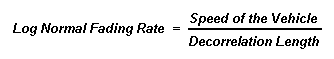
Range: 1 to 1000 m
Default: 20 m
Sets the decorrelation length (m) for the configured path. Decorrelation length is the average size of objects that cause the shadowing that results in log normal fading. It is activated when Log Normal is enabled or is implied by Suzuki fading. Changing the decorrelation length for one path will change it for all paths.
The following formula determines the rate at which slow fading will occur: