This procedure requires an E4438C-UN7 (internal bit error rate analyzer).
When clock and gate signals generated by the signal generator are used to perform BER analysis, it is important to realize that the test signal transmitted by the signal generator experiences a propagation delay through the device under test. As a result, the demodulated loopback signal must be realigned in time with the clock and gate signals at the input of the BER analyzer (see figure below). Delay control over the clock and gate signals is provided by the software to enable realignment with the test signal at the input of the BER analyzer.
If the propagation delay characteristics for the device under test are known, enter the delay value in the field during configuration. The clock and gate signals associated with the waveform will be delayed by the indicated amount during waveform playback. The resolution of the parameter is directly coupled to the oversampling ratio setting. It can be determined by dividing the symbol period (1 μs) by the oversampling ratio. To increase the incremental delay resolution, increase the oversampling ratio of the configured waveform. When doing so, remember that increasing the oversampling ratio also increases the projected length of the waveform.
If the delay parameter is unknown, leave the default value (0 μs) in the field and finish configuring the waveform. After the waveform has been calculated, the calibration utility can be used to determine the delay characteristics of the device under test.
The following example procedure shows how to make calibration and BER test.
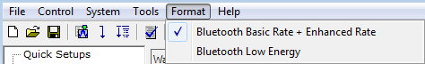
Select from the Format drop-down menu.
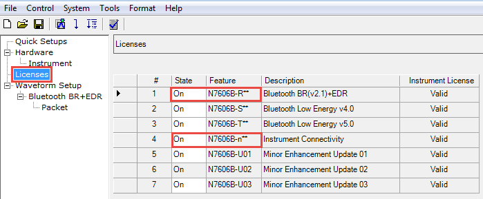
Click in the tree view on the left to ensure that the states for and are set to On.
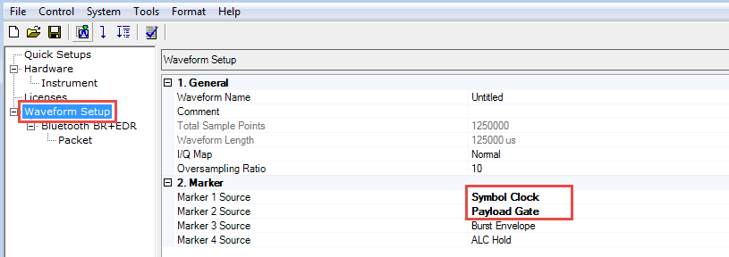
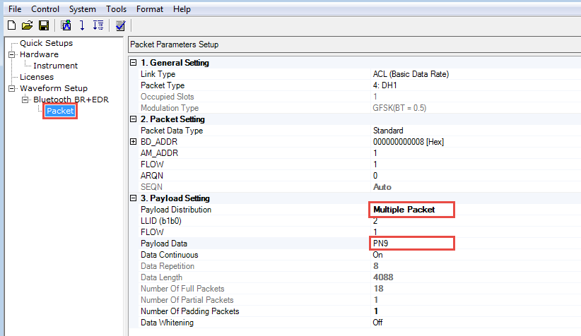
Click in the tree view.
Set to .
Set to .
Click in the tree view on the left.
Set to .
Click the  in the tool bar to generate and download the waveform to the
signal generator.
in the tool bar to generate and download the waveform to the
signal generator.
Click
in the tree view, then click  to configure form.
Set to
Set to
Set to
Set to
Once configured, initiate the BER test sequence by pressing the  button. A plot of BER vs. clock/gate
delay will be incrementally filled in as each BER test in the sweep is
completed. Click button to start delay calibration.
When finished, use the arrow buttons to determine the delay value resulting
in the lowest bit error rate.
button. A plot of BER vs. clock/gate
delay will be incrementally filled in as each BER test in the sweep is
completed. Click button to start delay calibration.
When finished, use the arrow buttons to determine the delay value resulting
in the lowest bit error rate.
Click  and Close Window.
Re-download the waveform and read BER test results from signal generator.