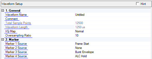
Click in the tree view displays the Waveform Setup
Enter an alpha-numeric waveform file name, up to 22 characters in length. The name can include spaces and some special characters: _ $ & # + - [ ]. You can enter a name with more than 22 characters, but when you click outside of the cell, the software truncates the name to 22 characters.
The name you define here is displayed on the signal generator when you download the waveform.
Enter an alpha-numeric comment up to 32 characters in length. The comment resides in the file header and can include spaces and special characters.
View the generated waveform length (number of points). You cannot edit this cell.
View the generated waveform length (in μs). You cannot edit this cell.
Choice: Normal | Inverted
Default: Normal
Double-click or use the drop-down menu to select a normal or inverted I/Q signal. Select Invert to swap the I and Q signals.
Range: 2 to 100
Default: 10
Set the number of samples calculated per I/Q symbol.
A larger oversampling ratio results in a more completely filtered image, but uses more waveform memory because it increases the number of waveform points. A smaller oversampling ratio reduces waveform file size, but reduces performance. Notice that the Total Sample Points is updated as the Oversampling Ratio setting is changed.
Double-click or use the drop-down menu to select the type of signal output for each marker. The markers are set to go high for selected events.
The software uses Marker 3 to control the RF blanking and Marker 4 for ALC settings. These settings should NOT be changed unless you know how the changes will affect the waveform playback.
: selects no signal output. This is the default for Marker 2.
: selects high signal output at the start point of the waveform.
: selects high signal output at each frame start. This is the default for Marker 1.
: selects high signal output when the burst (except for gap) is active. This is the default for Marker 3.
: assigns a specific marker to activate the automatic leveling control (ALC) function. When enabled, the ALC constantly monitors and controls the RF output power of the ESG. This is the default setting for Marker 4.
: selects high signal output at the middle of each symbol.
: selects high signal output at symbols that are modulated with payload data.