This topic is based on the ETSI TS 102 754 V1.3.1 (2013-03) Technical Specification.
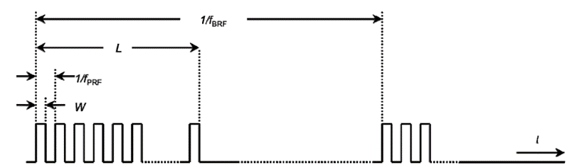
The Detect And Avoid (DAA) based interference mitigation architecture is used for UWB devices to protect active victim services. The general structure of radio location bursts is given in Figure 1. The test patterns to be used throughout testing, together with the relevant radar frequencies of operation are given in Table D.1.
Figure 1: General structure of the bursts for DAA radio location test transmissions
Table D.1: Parameters of radio location test signals
|
Radar Test Frequencies (see Note 11) |
Radar test signal |
Pulse width W (μs) (see Note 5) |
Pulse repetition frequency fPRF [pps] (see Note 13) |
Pulses per burst [PPB] |
Burst repetition frequency fBRF [bps] |
Detection probability with 50% channel load |
|---|---|---|---|---|---|---|
|
f1 = 3,1 GHz f1 < f2 < f3 f3 = 3,4 GHz |
1 - Variable |
20, 30, 40 |
400 to 1 400 (see Note 6) |
10 to 60 |
0,2 to 0,08 |
Pd > 90% |
|
f1 = 3,1 GHz f1 < f2 < f3 f3 = 3,4 GHz |
2 - Variable |
1 (see Note 14), 10, 20, 40, 60, 100 |
100 to 500 (see Note 6) |
2 to 5 |
0,2 to 0, 08 |
Pd > 90% |
|
f1 = 8,55 GHz f1 < f2 < f3 f3 = 8,95 GHz |
3 - Variable |
1, 2, 5, 10, 15 |
5 000 to 15 000 |
20 to 560 |
2,0 to 0, 22 |
Pd > 90% |
NOTE 1: This represents the number of pulses seen at the UWB DAA radio device per radar scan:
N = [{antenna beamwidth (deg)} × {pulse repetition rate (pps)}] / [{scan rate (deg/s)}].
Chose randomly a number of pulses in the given limits.
L = PPB × 1/fPRF, Burst length in seconds.
NOTE 2: The test signals above only contain a single burst of pulses.
NOTE 3: The number of pulses per burst given in this table simulates real radar systems and takes into account the effects of pulse repetition rate and pulse width on the detection probability for a single burst.
NOTE 4: Pd gives the probability of detection per simulated radar burst and represents a minimum level of detection performance under defined conditions - in this case a 50% traffic load.
Therefore Pd does not represent the overall detection probability for any particular radar under real life conditions. In general 2 sequential bursts are needed to achieve a real life detection rate of better that 99% for any radar that falls within the scope of this table.
NOTE 5: The pulse width used in these tests is assumed to be representative of real radar systems with different pulse widths and different modulations. The pulse width is assumed to have an accuracy of ±10 %.
NOTE 6: Chose PRF randomly in the given range.
NOTE 7: The burst repetition frequency fBRF is used in the In-Service Monitoring test setup.
NOTE 8: The radar test signals 1 and 2 are to be used for the DAA radio device test in the band 3,1 GHz to 3,4 GHz.
NOTE 9: The radar test signals 3 are to be used for the DAA radio device test in the 8,5 GHz to 9 GHz.
NOTE 10: Pulses have instantaneous bandwidth of 0,5 MHz, 1 MHz, 2 MHz or 5 MHz. Modulation types can be LFM, BPSK.
NOTE 11: The Radar Test Frequency f2 shall be arbitrarily chosen between the f1 and f3.
NOTE 12: Suitable combinations of PPB and fBRF are to be selected whereby for radar test signals 1 to 3, the minimum number of pulses per second is 2, 5 and 40 respectively. This clarifies note 1.
NOTE 13: The granularity for each radar test signal is 11 evenly distributed cases. The respective step sizes for radar test signals 1 to 3 are 100, 40 and 1 000.
NOTE 14: For the pulse width of 1 µs the number pulses/burst should be arbitrarily chosen between 20 PPB and 50 PPB.