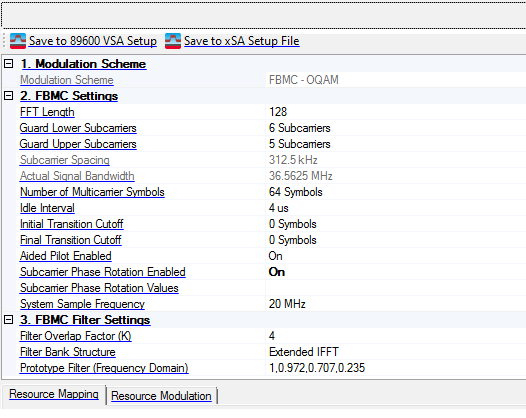

This feature saves the Custom Modulation configuration as a 89600B VSA setup file, simplifying VSA configuration so you can quickly demodulate the signal.
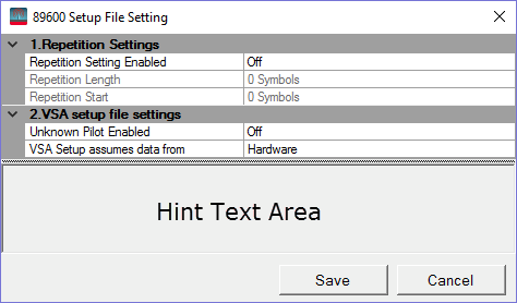
The 89600B VSA uses a parameter called Resource Repeat Index to reduce the length of the Resource Map and Resource Modulation arrays. The N7608C software, however, uses Repetition Start and Repetition Length to indicate the periodicity (how many symbols are repeated) between OFDM symbols. Therefore, a window appears, providing an opportunity for you to adjust these values before saving the setup file.
To support the "Frame Definition" parameters, recently added to 89600 VSA Custom OFDM Demod Properties, the Name of Resource Block should be configured as below:
The part in square brackets "[]_" of the Name will be mapped to the Frame Part and Allocation name of VSA, e.g. "[FP1]_Alloc1" maps to VSA's Frame Part "FP1" and Allocation "Alloc1"
All the Resource Blocks with Name that does NOT have the "[]_" identifier will be put into one VSA Frame Part with default name "FramePart0"
When exporting a VSA setup for an FBMC signal, not all the signal configurations can be correctly demodulated by VSA software. The signal configuration must follow the rules below to achieve a good demodulation:
The signal should be a burst signal, with non-zero idle interval.
The number of preamble symbols should be larger than the overlap factor (K).
The location of the pilot should be staggered, meaning that adjacent resource elements of a pilot (±2 symbols in time domain and ±1 subcarrier in frequency domain) should not be a pilot.

Choices: On | Off
Default: Off
Enable or disable the repetition setting for the setx file to be exported. If symbol mapping has repeatability, select On to set Repetition Start and Repetition Length to reduce the VSA setup file size, otherwise it should be set to Off.
Range: 0 to Number of OFDM Symbols
Default: 0
Set the repetition length (in symbols) when generating the 89600 setup file. This parameter indicates the periodicity of the resource setting. Set to zero if there is no periodicity.
Only some of the basic OFDM parameters are saved to the 89600B setup file. You may need to adjust other parameters in the 89600B VSA to achieve optimum demodulation results.
Range: 0 to Number of OFDM Symbols
Default: 0
Set the repetition start (in symbols) when generating the 89600 setup file. If the Repetition Length is not zero, this parameter indicates the start symbol index for repetition.
Choices: On | Off
Default: Off
Enable or disable the unknown pilot. If enabled, the pilot resource element will be treated as unknown pilot on the VSA side.
Choices: Hardware | Recording
Default: Hardware
Set the data source in the saved VSA setx file.
Saves the configuration as an X-Series Signal Analyzers (xSA) setup file (*.xml).
Choices: FBMC-OQAM | UFMC | GFDM | F-OFDM
Default: FBMC-OQAM
Select the modulation scheme for 5G.
Range: 4 to 16384
Default: 128
Set the FFT length of the OFDM signal. The input can now be set with non-powers of 2.
If the input FFT length is not divisible by 2, the input value is subtracted by one. For example, an input of 5 will become a valid value of 4.
An input of 6 is now valid for this feature.
Range: 0 to FFT Length/2
Default: 6
Sets the number of lower guard subcarriers. No data will be transmitted on these subcarriers.
Range: 0 - (FFT Length - Guard Lower Subcarriers - 1)
Default: 5
Set the number of upper guard subcarriers. No data will be transmitted on these subcarriers.
Display the subcarrier spacing. This value is read-only and will be automatically updated with FFT Length and System Sample Frequency change.
Display the actual signal bandwidth of the used subcarriers (FFT Length - Guard Lower Subcarriers - Guard Upper Subcarriers).
Range: 1 to 8000
Default: 64
Set the number of Multicarrier symbols in a frame, which usually includes preamble symbols and data symbols.
Range: 0 to 200 ms
Default: 4 us
Set the idle interval in-between OFDM frames in seconds. When idle interval is set to zero, a continuous waveform will be generated.
Range: 0 - (K - 0.5)
Default: 0
Set the number of cutoff symbols in the initial transition.
Range: 0 - (K - 0.5)
Default: 0
Set the number of cutoff symbols in the final transition.
Choices: On | Off
Default: On
Enable or disable the aided pilot for FBMC signal.
Choices: On | Off
Default: Off
Enable or disable the phase rotation for each subcarrier.
Opens a file management window where you can select the .txt or .csv file, containing phase rotation data. The file data must follow these rules:
Each line corresponding to a subcarrier, starting from the lowest subcarrier to highest subcarrier except guard.
If there is only one column in the file, each value will be treated as the phase to be rotated, the unit is degree.
If there are two columns in the file, each pair values will be treated as the I/Q value represent the phase rotation.
If # of phase values > # of valid subcarrier, we just use available values. (valid subcarrier means the FFT length minus upper and lower guard)
If # of phase values < # of valid subcarrier, we use values available then no phase rotation for remaining subcarriers.
Range: 1 kHz to 4 GHz
Default: 40 MHz
Set the system sampling rate in Hz.
Range: 2 to 8
Default: 4
Set the filter overlap factor (K) for FBMC signal.
Choices: Extend IFFT | Polyphase Network
Default: Extend IFFT
Select the filter bank structure for FBMC signal.
Opens a ![]() Filter Editor window where you can import, export, and edit FBMC filter coefficients. A convenient plot of the filter's frequency response is displayed and updates as coefficients are changed. Imported and exported coefficient files are in text (*.txt) or comma-separated values (*.csv) format.
Filter Editor window where you can import, export, and edit FBMC filter coefficients. A convenient plot of the filter's frequency response is displayed and updates as coefficients are changed. Imported and exported coefficient files are in text (*.txt) or comma-separated values (*.csv) format.