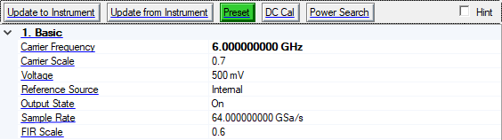
To access the instrument settings, click in the tree view. If there is more than one instrument connection, there will be a corresponding number of Instrument listings in the tree view. The figure below shows the Instrument property grid when connected to an M8195A AWG.
Click this button to send the parameters to the connected instrument.
Click this button to retrieve the parameters from the connected instrument.
Click this button to set the signal generator to a factory-defined or user-defined state.
Refer to the signal generator's user's guide for information on setting a user-defined state.
Click the DC Cal button to execute an I/Q DC calibration to minimize errors associated with offset voltages.
DC Cal minimizes I/Q offset errors for a single frequency only and must be repeated if the signal generator's settings change.
Download a waveform to set the correct parameters for the target instrument and activate this button.
Click the Power Search button to execute a manual power search calibration. This is an internal calibration routine that improves output power accuracy when the ALC is turned off. A power search is recommended for pulse-modulated signals with pulse-widths less than two microseconds.
Download a waveform to set the correct parameters for the target instrument.
Range: 0 to 32 GHz
Set the value of the carrier frequency. Please note that the carrier frequency value only takes effect after downloading the waveform.
Range: 0 to 2.82843
Set the amplitude scale of the output signal.
Range: 75 mV to 1 V
Set the amplitude of the output signal.
Choices: External | Backplane | Internal
Default: Internal
Double-click or use the drop-down menu to select the channel clock source.
Internal - Use the internal sample clock.
External - Use the external sample clock provided to the SAMPLE CLK IN connector on the M8195A front panel.
Choice: On | Off
Default: On
Double-click or use the drop-down menu to control the signal generator’s RF output state.
Range: 54 GHz to 65 GHz
Set the internal sample clock rate, the samples in the waveform are resampled from the sample frequency taken from the waveform header to the sample frequency currently configured in the M8195A. Use abbreviations for faster entry (example: 1g = 1.0 GHz).
Range: 0.1 to 1
Set the FIR filter scaling factor.