Choices: WLAN: IEEE 802.11a | DAB: Mode I | DVB-T/H: 2K 1/8 | DVB-T/H: 1K 1/32 | ISDB-T (Mode3, 1+12) | DOCSIS 3.1 Upstream | DOCSIS 3.1 Downstream | CDR TxMode1, Spectrum Mode 2 | CDR TxMode1, Spectrum Mode 9 | CDR TxMode1, Spectrum Mode 10 | DRM: ModeB 20K | LTE: Downlink 5MHz | LTE: Uplink 5 MHz (without half subcarrier shift)
Use this  drop-down menu to choose a quick setup.
This feature saves the Custom Modulation configuration as a 89600B VSA setup file, simplifying VSA configuration so you can quickly demodulate the signal.
The 89600B VSA uses a parameter called Resource Repeat Index to reduce the length of the Resource Map and Resource Modulation arrays. The N7608B software, however, uses Repetition Start and Repetition Length to indicate the periodicity (how many symbols are repeated) between OFDM symbols. Therefore, a window appears, providing an opportunity for you to adjust these values before saving the setup file.
Choices: On | Off
Default: Off
Enable or disable the repetition setting for the setx file to be exported. If symbol mapping has repeatability, select On to set Repetition Start and Repetition Length to reduce the VSA setup file size, otherwise it should be set to Off.
Range: 0 to Number of OFDM Symbols
Default: 0
Set the repetition length (in symbols) when generating the 89600 setup file. This parameter indicates the periodicity of the resource setting. Set to zero if there is no periodicity.
Only some of the basic OFDM parameters are saved to the 89600B setup file. You may need to adjust other parameters in the 89600B VSA to achieve optimum demodulation results.
Range: 0 to Number of OFDM Symbols
Default: 0
Set the repetition start (in symbols) when generating the 89600 setup file. If the Repetition Length is not zero, this parameter indicates the start symbol index for repetition.
Choices: On | Off
Default: Off
Enable or disable the unknown pilot. If enabled, the pilot resource element will be treated as unknown pilot on the VSA side.
Range: 0 to 200 ms
Default: 4 us
Set the idle interval in-between OFDM frames in seconds. When idle interval is set to zero, a continuous waveform will be generated.
Range: 1 kHz to 4 GHz
Default: 20 MHz
Set the system sampling rate in Hz.
Range: 0° to 360°
Default: 0°
Enter the initial phase of the carrier signal in degrees. A fixed phase rotation will be added to the generated OFDM signal. You can assign different intial phases to different waveforms for the beamforming test.
Default: 0 Hz
Apply a frequency offset to the generated baseband IQ. The max offset is limited by the current sampling rate. To apply a larger frequency offset, you will need to increase the OSR to a proper value.
Max offset = System Sample Frequency * Oversampling Ratio / 2.56 - System Sample Frequency / 2
Range: 4 to 16384
Default: 64
Set the FFT length of the OFDM signal. This value will be clipped to the nearest power of 2.
Opens the Cyclic Prefix Length editor for configuring the length of the OFDM symbols within a frame. You can set each symbol individually or use a preset configuration.
Range: 0 to FFT Length/2
Default: 6
Set the number of lower guard subcarriers. No data will be transmitted on these subcarriers.
Range: 0 to FFT Length/2
Default: 5
Set the number of upper guard subcarriers. No data will be transmitted on these subcarriers.
Displays the subcarrier spacing (System Sample Frequency / FFT Length). This value is read-only and automatically updates with changes to FFT Length and System Sample Frequency.
Displays the actual signal bandwidth of the used subcarriers (FFT Length - Guard Lower Subcarriers - Guard Upper Subcarriers).
Range: 1 to 2000
Default: 64
Set the number of OFDM symbols in a frame, which usually includes preamble symbols and data symbols.
Choices: First Symbol | Preamble Symbol(s) | All Symbol(s)
Default: First Symbol
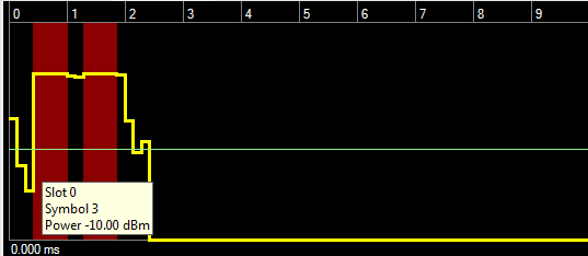
In most cases, the power level for an OFDM signal is not constant across all the symbols. This parameter allows you to choose which symbols in the waveform will have their power associated with the amplitude displayed on instrument front panel. Other parts will have a relative power gap to the referenced part based on the rms ratio. Preamble Symbol(s) are the symbols mapped to Preamble in resource mapping. If there is no preamble symbol, the first symbol will be used.
Choices: None | Gaussian | Root Nyquist | Nyquist | Rectangle | User Defined
Default: None
Select the filter type to be applied to the waveform.
Range: 0.01 to 1.0
Default: 0.5
Sets the alpha factor of the Root Nyquist or Nyquist filter.
Opens a Filter Editor window where you can import, export, and edit filter coefficients. A convenient plot of the filter's impulse response is displayed and updates as coefficients are changed. Imported and exported coefficient files are in text (*.txt) or comma-separated values (*.csv) format.
Range: 0.1 to 1.0
Default: 0.5
Sets the BT product of the Gaussian filter.
Range: 1 to 1000
Default: 32
Sets the length of the filter in symbols.
Range: 0 to 0.5
Default: 0.005
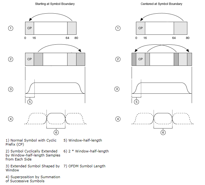
Set the windowing length used to smooth OFDM symbol transitions. Specify this value as a fraction of FFT Length, not the percentage.
Choices: Centered at Symbol Boundary | Starting at Symbol Boundary
Default: Centered at Symbol Boundary
Select the windowing method applied to the OFDM symbol transitions. The raised cosine window can be centered at the OFDM symbol boundary, or starting from the OFDM symbol boundary. View image.
Centered at Symbol Boundary specifies that the window is applied with its center at the boundary between two orthogonal frequency division multiplexing (OFDM) symbols.
Starting at Symbol Boundary specifies that the window is applied with its starting position at the boundary between two OFDM symbols.