 button
on the toolbar allows you to save an already configured antenna pattern
to a file. Clicking the button launches the Save As dialog box for navigating to a location and saving the file.
button
on the toolbar allows you to save an already configured antenna pattern
to a file. Clicking the button launches the Save As dialog box for navigating to a location and saving the file.The Save Antenna  button
on the toolbar allows you to save an already configured antenna pattern
to a file. Clicking the button launches the Save As dialog box for navigating to a location and saving the file.
The  antenna pattern file
is in *.csv format with the header in the first line like this:
AGILENT_ANTENNA_PATTERN, version number, file name, elevation resolution value, azimuth resolution value, azimuth rotation value, generation date time, Agilent Technologies
The rows and columns represent the azimuth and elevation blocks, respectively. For example, the first data column represents the gain values for elevation [0° - 10°] across the whole azimuth range. The second data row represents the gain values for azimuth [30° - 60°] across the whole elevation range. Change the antenna pattern by editing the cell values.
The antenna pattern is not saved with the other scenario generation parameters using the Save button.
The Recall Antenna  button on the toolbar allows you to recall a previously saved pattern from a file. Clicking the button launches the Open dialog box for navigating to a location and selecting a file.
The compass on the top-left corner provides the orientation reference for the sky-view gain mask. The compass indicator changes, depending on which Scenario Type (static or dynamic) you select for the Scenario Generator.
For a static scenario,
the gain mask configuration uses an absolute north/south/east/west (NSEW)
coordinate system, in which 0 degrees azimuth indicates north. The compass
indicator in the display shows  NSEW
for the gain mask configuration. During the scenario generation, when
a satellite appears in a cell specified by an elevation/azimuth pair,
its power will be attenuated by the assigned gain value.
For a dynamic scenario,
the gain mask configuration uses a forward/backward/left/right (FBLR)
system that is relative to the moving receiver, in which 0 degrees azimuth
is always pointing forward. The compass indicator in the display shows
 FBLR
for the gain mask configuration. When the receiver is in motion, the scenario
generator translates the gain mask into the NSEW coordinate system by
rotating the azimuth and elevation, based on the receiver's motion at
each sample point. This simulates a GPS receiver mounted in a moving car
with the gain mask configured to reflect some fixed attenuation from the
car body. When the car changes direction, the gain mask will have a corresponding
azimuth rotation. When the car climbs or goes down a slope, the gain mask
will have an elevation rotation.
To eliminate possible errors resulting from an imperfect NMEA message file, error checking is applied to the elevation rotation. For example, if you are using a GGA file recorded from a GPS receiver and the data was sampled at a low rate, whenever the receiver becomes stationary (no changes to longitude or latitude), the scenario generator may erroneously calculate a +/-90 degree elevation rotation. To prevent this type of error, the software does not apply elevation rotation in the following cases:
Whenever the receiver is moving at a speed that is less than 1 m/s.
Whenever the receiver is climbing a slope greater than 60 degrees or is going down a slope less than –60 degrees, which is highly unlikely in the real world.
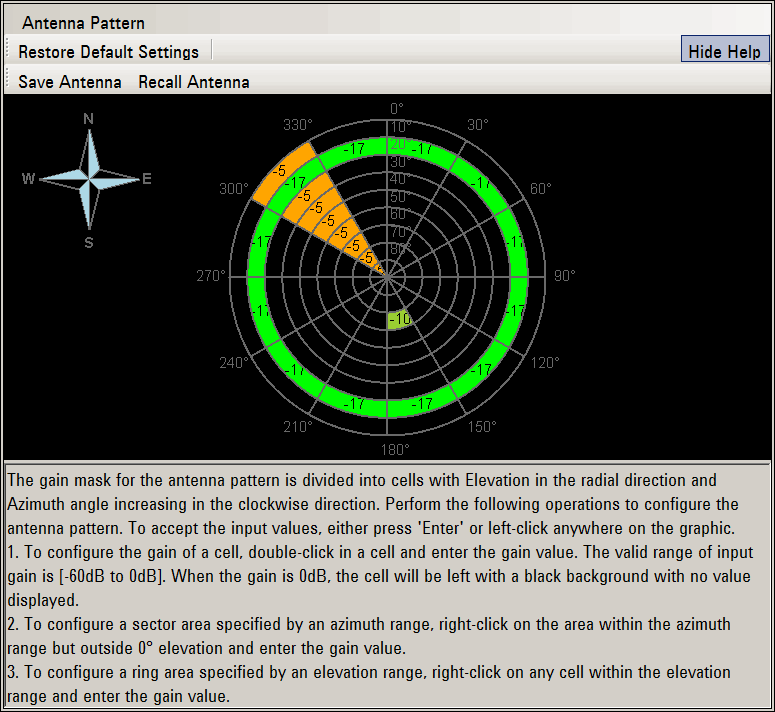
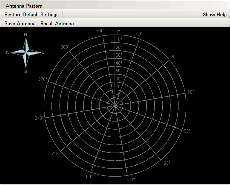
Configure the Antenna Pattern by filling the cells in the sky-view with proper gain values to form a gain mask. The gain mask for the antenna pattern is divided into cells with elevation in the radial direction and azimuth angle increasing in the clockwise direction. Configure the antenna pattern using the methods below. To accept the input values, either press Enter or click anywhere on the graphic.
To configure the gain of a cell, double-click in a cell and enter the gain value.
The valid range of input gain is [-60 dB to 0 dB]. When the gain is 0 dB, the cell will remain black with no value displayed.
To configure a sector area specified by an azimuth range, right-click in the area within the azimuth range but outside 0° elevation and enter the gain value.
To configure a ring area specified by an elevation range, right-click on any cells within the elevation range and enter the gain value.

The default antenna pattern with 0° azimuth pointing to North is called the base pattern. To make the pattern rotate from the base pattern with a specified angle, change Azimuth Rotation in the Scenario Generator tab. Antenna Pattern rotation is useful for modeling receiver antenna that will change its orientation in different test environments.
The figure below shows an antenna pattern with 20° of rotation.

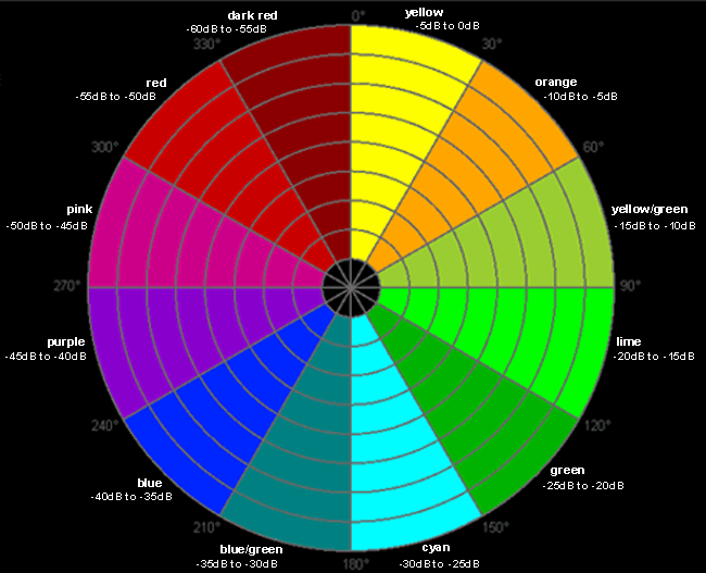
The figure and table below show the colors used for gain value ranges on the sky-view gain mask.

|
Gain Value Range |
Cell Color |
|---|---|
|
-5 dB to 0 dB |
Yellow |
|
-10 dB to -5 dB |
Orange |
|
-15 dB to -10 dB |
Yellow/Green |
|
-20 dB to -15 dB |
Lime |
|
-25 dB to -20 dB |
Green |
|
-30 dB to -25 dB |
Cyan |
|
-35 dB to -30 dB |
Blue/Green |
|
-40 dB to -35 dB |
Blue |
|
-45 dB to -40 dB |
Purple |
|
-50 dB to -45 dB |
Pink |
|
-55 dB to -50 dB |
Red |
|
-60 dB to -55 dB |
Dark Red |