Choice: On | Off
Default: On
Double-click or use the drop-down menu to set the state of the carrier ON or OFF.
Range: -12.5 to 12.5 MHz
Default: 0.000000 Hz
Set the frequency offset for the carrier relative to the signal generator’s frequency setting.
Range: 0.00 to 359.00 deg
Default: 0.00 deg
Set the initial phase of the carrier.
Range: -50.00 to 0.00 dB
Default: 0.00 dB
Set the carrier’s power relative to the signal generator’s amplitude setting.
Range: 1Hz to 300 kHz
Default: 75.000 kHz
Frequency deviation is used in FM radio to describe the maximum instantaneous difference between an FM modulated carrier frequency, and the nominal carrier frequency.
Choice: Percentage | Frequency
Default: Percentage
Double-click or use the drop-down menu to set the FM Deviation Unit to percentage or frequency. Pilot Deviation and RDS Deviation will be set in the selected FM Deviation Unit accordingly.
Choice: True | False
Default: True
Double-click or use the drop-down menu to select whether the FM deviation is normalized. This key is only visible when FM Deviation Unit is set to percentage.
True − the FM Deviation value is used as corresponding to the peak value of the baseband modulating signal, including all signals such as audio, pilot and RDS.
False − the FM Deviation is used as a reference and corresponding to the amplitude of 1 V. Then the percentages of ”Audio Deviation”, ”Pilot Deviation” and ”RDS Deviation” can be set corresponding to it. However, the actual FM deviation may not be the value set for FM Deviation. Especially when Pre-emphasis is used, the audio signal will pass a filter which will significantly enlarge the signal level in higher frequency. To prevent the VCO used to generate the FM signal overload, you need to set an appropriate value to Normalized Audio Frequency cell . For more information, refer to Pre-emphasis.
Choice: On | Off
Default: On
Set pilot status.
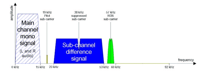
When transmitted in stereo, it's preferable to synchronize the RDS subcarrier with the 19 kHz pilot signal, rather than leave these two signals in complete independence. In fact substantial inter-modulation may be produced between the 3rd harmonic of the pilot signal and the RDS signal, generating an unwanted beat which may be audible.
The following picture shows the baseband layout of FM broadcasting:
Range: 0.1% to 20%
Default: 10.0 %
The percentage of frequency deviation, since the tolerance on the frequency of the 19 kHz pilot-tone is from -2 Hz to 2 Hz.
Range: 14.000 kHz to 24.000 kHz
Default: 19.000 kHz
In FM stereo broadcasting, a pilot tone of 19 kHz indicates that there is stereophonic information at 38 kHz (19×2, the second harmonic of the pilot). The receiver doubles the frequency of the pilot tone and uses it as a phase reference to demodulate the stereo information.
Range: 0.00 deg to 359.00 deg
Default: 0.00 deg
Set the initial phase of the pilot signal.
Range: 34.000 kHz to 42.000 kHz
Default: 38.000 kHz
Set the stereo frequency.
Range: 0.00 deg to 359.00 deg
Default: 0.00 deg
Set the initial phase of the stereo signal.
Range: 1% to 100%
Default: 100 %
Set the percentage of audio deviation.
Choice: L Only | R Only | L = R | L = -R | L ≠ R
Default: L = R
Select the type of audio source.
Choice: Tones | Wav File
Default: Tones
Set the format of audio source, which could be Tones or Wav File. Notice that Pre-emphasis is effective only when audio source is multi-tone.
Wav File can only be enabled when Normalized is True.
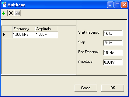
Set the tone (s) of the left channel in the following procedures.
Click
on the cell of Left Tone (s) , and a  will appear on the right end of the cell. Click on the button,
and a dialog for multi-tone configuration will
pop up.
will appear on the right end of the cell. Click on the button,
and a dialog for multi-tone configuration will
pop up.
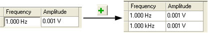
 Add a tone
Click on button, a new tone with default frequency
and amplitude will be generated.
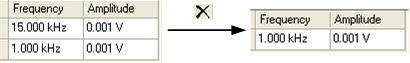
 Remove a tone
Click on button, an existing tone will be eliminated.
Notice that the items on top will be removed first.
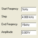
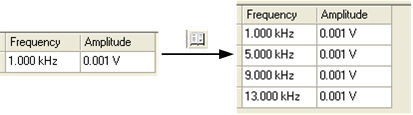
 Add multitone
Click on button, a list of tones with configured frequencies
and amplitudes will be displayed. You can specify the , , and
through the ![]() dialog on the right side,
here has been set to 4kHz
as an example.
dialog on the right side,
here has been set to 4kHz
as an example.
Set the tone(s) of the right channel. For more information about the procedures, please refer to the Left Tone (s) setup.
Choice: Off | 50 us | 75 us
Default: Off
In FM transceiver, pre-emphasis and de-emphasis is always adopted to solve the low SNR problem of high frequency band. Pre-emphasis refers to raising high frequency components of the input signal at the transmitter side.
However, the maximum frequency deviation after FM may increase since the high frequency components has been lifted, and it might exceed the spectrum width allowed by the original channel. That’s why the signal ought to be attenuated after pre-emphasis, before modulation, in order to keep the frequency deviation constant.
When Pre-emphasis is turned on and Normalized is true, the audio signal will pass a filter shown in Figure 1. When Normalized is false and Normalized Audio Frequency cell is set to a value (for example, 15 kHz), the pre-emphasis gain is 0dB at 15 kHz. That means the values of y-Axis in the Figure 1 will be normalized by 13.66dB. This case is commonly used because the input range of VCO is limited.
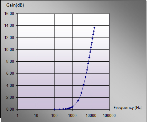
Figure 1 The relationship curve between Frequency and Gain (50us)
Default: 15.000 kHz
Sets the normalized audio frequency. This value will affect the pre-emphasis filter used. For more details, refer to Pre-emphasis.
This cell is only visible when Normalized is set to false and Pre-emphasis is turned on.
Choice: On |Off
Default: On
Radio Data System, or RDS, is a standard from the European Broadcasting Union for sending small amounts of digital information.
Range: 0.1% to 20%
Default: 6.0%
Range: 53 to 61 kHz
Default: 57 kHz
Range: 0.00 deg to 359 deg
Default: 0.00 deg
Choice: Nyquist | Root Nyquist
Default: Root Nyquist
Set the filter type of RDS.
Range: 0.05 to 1
Default: 1
Set the roll-off factor of a root raised cosine filter or a raised cosine filter.
Choice: Messages | Pattern Bits
Default: Messages
Set the RDS payload type.
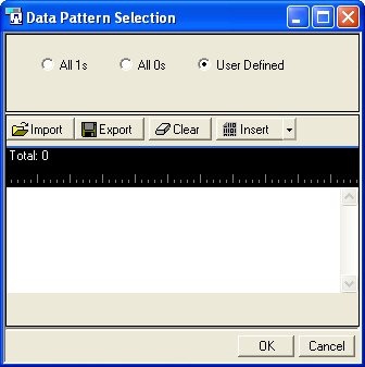
Choice: All 1s| All 0s| User defined
Default: All 1s
Set the RDS pattern bits.
Double-click or use the drop-down menu to set whether the CRC (Cyclic redundancy check) is inserted into the RDS pattern bits.