
Select in the , shown as follows.
Clicking in the tree view displays the panes in the parameter view where you can configure a DAB waveform and download it to the ESG or EXG/MXG Vector Signal Generator. This software will do real-time coupling and clipping on the DAB waveform parameters that you input and display the coupled and clipped values immediately.
The parameters configuration for DAB waveforms can be divided into four levels, and each level has its specific parameter set as listed below in detail.
Waveform Setup – Waveforms can consist of up to 12 carriers in a single waveform. In the waveform setup window, you can add and remove carriers that you require. Set the waveform properties, such as Oversampling Ratio, which allows you to quickly assess your setup.
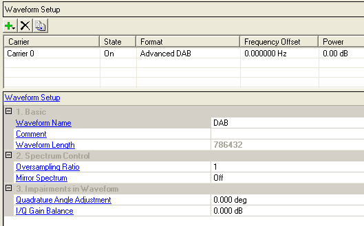
This table enables you to view the key parameters for each carrier in the waveform. You can also add or delete carriers using the buttons above the table (see descriptions below). Double-clicking a carrier row activates the setup tables for that carrier. You can use a maximum of 12 carriers in the waveforms and each carrier can be configured independently.
Click  to open a drop-down
menu which allows you to add a carrier to the current configuration. The
new carrier is added immediately above the currently highlighted carrier
in the Carrier Configuration Summary Table.
to open a drop-down
menu which allows you to add a carrier to the current configuration. The
new carrier is added immediately above the currently highlighted carrier
in the Carrier Configuration Summary Table.
Click  to delete the highlighted
carriers in the Carrier Configuration Summary Table.
to delete the highlighted
carriers in the Carrier Configuration Summary Table.
Click  to copy the highlighted carrier and appends
the copy to the bottom of the carrier list.
to copy the highlighted carrier and appends
the copy to the bottom of the carrier list.
In a multi-carrier configuration, the settings for each carrier are not coupled. Therefore, it is important that you pay special attention to the following.
When setting frequency offset for each carrier, you should try to make the spectrum symmetric to the carrier frequency. For example, if there are two carriers, it is better to set frequency offsets as -0.856 MHz and 0.856 MHz instead of 0 and 1.712 MHz.
The Oversampling Ratio (default setting 1) may need to be increased to make sure the ARB Sample Clock * Oversampling Ratio > bandwidth of the signal.
The play time of each carrier needs to be the same. If not, there will be errors and the waveform can't be generated. The play time is Number of Transmission Frames * Frame length. The frame lengths for each mode are 96 ms for Mode I, 24 ms for Mode II, 24 ms for Mode III, and 48 ms for Mode IV.
If audio test is needed, it's better to increase the 'Number of Transmission Frames' for longer play time, for example 6 secs.
Enter an alpha-numeric waveform file name of up to 22 characters. The name can include spaces and the following special characters: _ $ & # + - [ ]. If you enter a name with more than 22 characters, the software truncates the name to 22 characters when you click outside of the cell. The default name is DAB.
The name you define here is displayed on the signal generator when you download the waveform.
Enter an alpha-numeric comment of up to 32 characters. You can enter a separate comment for each waveform.
View the waveform length, displayed in points. You cannot edit this cell. The software automatically sets this value.
Increasing the or the will increase the waveform length.
If you build a waveform from multiple carriers, Waveform Length is specific to an individual carrier. If the carrier Waveform Lengths are different, the waveform can't be generated.
Range: 1 to 48
Default: 1
Set the oversampling ratio of the baseband signal.
Choice: On | Off
Default: Off
Double-click or use the drop-down menu to swap the I and Q waveforms.
This parameters is used during the correction operation to account for low side up conversion between the signal and the spectrum analyzer.
Range: -90.000 to 90.000 degrees
Default: 0.000 deg
Set the baseband quadrature phase angle in degrees.
Range: -10.000 to 10.000 dB
Default: 0.000 dB
Set the baseband quadrature gain balance, in dB.