Generating signal 1, with the carrier parameter settings listed below.
-
Set the to ,
-
Set the to
-
Set the to , and to .
The waveform spectrum of Signal 1 is as follows:
Generating signal 2, with the carrier parameter settings listed below.
The waveform spectrum of Signal 2 is shown below:
-
Set to
-
Set to
-
The other settings remain the same with Signal 1 based on Configuration
 :
:
Notice that a FM signal with pilot(19KHz) has been generated.
Generating signal 3, with the carrier parameter settings listed below.
-
Set to
-
Set to
-
Set the to
-
Set the to , and to .
The waveform spectrum of Signal 3 is shown below:
Comparing signal 2 and 3, it could be derived that when is , for single tone, has no effect.
For multiple tones signal, will change the relative relationship between multiple tones.
Generating signals with the carrier parameter settings listed below. Change from to to compare the results.
-
Set to
-
Set to
-
Set the to
-
Set the to , and to .
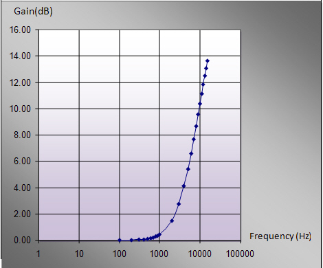
The audio signal will pass a filter like shown in the figure below.
Notice that there is a warning message shown as follows:

In this case, please reset FM Deviation or Oversampling ratio.
The waveform spectrum when is false:
Set to :
The Pre-emphasis gain is 0 dB at 15 kHz. That means the values of y-Axis in the figure will be normalized by 13.66dB.
This case is commonly used because the input range of VCO is limited.