Resource Structure | Frame Structure | Timeslot Structure
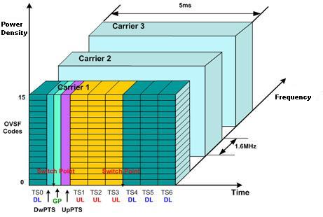
Signal Studio for TD-SCDMA/HSPA supports a multicarrier configuration that is a combination of time-division duplex (TDD) and synchronous CDMA. The downlink and uplink share the same 1.6 MHz carrier frequency band with seven timeslots per frame and 16 codes per timeslot.
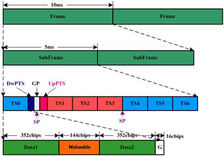
The frame structure consists of a 10 ms frame, subdivided into two 5 ms subframes, each one having seven traffic timeslots for uplink and downlink.TS0 is always assigned as the downlink direction an conveys control messages such as the broadcast channel (BCH) while TS1 is always allocated as uplink. In each subframe, there are two switching points that separate the uplink and the downlink. Using this frame structure, the 1.28Mcps TDD option can operate on both symmetric and asymmetric mode by properly configuring the number of downlink and uplink timeslots.

Within one 5 ms subframe, only two switching points (transition from uplink to downlink and vice versa) are allowed. The first switching point is at the GP (guard period) between the DwPTS (Downlink Pilot Timeslot) and the UpPTS (Uplink Pilot Timeslot). The second switching point can occur anywhere between the end of TS1 and the end of TS6. It is this second switching point that determines the traffic nature of a particular subframe, that is, symmetric or asymmetric. In asymmetric mode, at least one uplink timeslot and one downlink timeslot must be allocated for traffic (TS0 for downlink and TS1 for uplink). The position of the DwPTS, GP, and UpPTS is always between TS0 and TS1 whatever the level of asymmetry may be.
The DwPTS is used for downlink synchronization. During the cell search procedure, the UE acquires the timing of the DwPTS by correlating with the SYNC-DL code transmitted in the DwPTS. The UE must identify which SYNC-DL sequence is used out of 32 SYNC-DL possible sequences. Since each SYNC-DL is mapped to four basic midamble codes (there are 128 basic midamble codes in total), the UE can identify which basic midamble code is used at the Node-B. Knowing the basic midamble code also identifies the unique associated scrambling code.
The phase of the SYNC-DL can be used to signal the presence of the P-CCPCHs. Four consecutive phases (phase quadruple) of the SYNC-DL are used to indicate the presence of the P-CCPCH in the 4 subframes that follow.
|
|
Phase Quadruple |
Meaning |
|---|---|---|
|
S1 |
135, 45, 225, 135 |
Next four frames are P-CCPCHs |
|
S2 |
315, 225, 315, 45 |
Next four frames are not P-CCPCHs |
The guard period between DwPTS and UpPTS determines the maximum cell size. This main guard period is 96 chips long which is different from other normal guard periods of 16 chips between time slots. This 'super long’ guard period can support a cell radius of up to about 11 km for the uplink synchronization operation. The GP insures that a UE transmitting the UpPTS does not disturb the reception of the DwPTS for other close-by UEs.
The UpPTS is used by Node B to determine the received power level and the received timing from the UE. In order to reduce interference to traffic channels resulting from the unsynchronized uplink, the first transmission from the UE at the uplink direction has to be in the UpPTS. The timing used for the UpPTS transmission is estimated from the received power level of the DwPTS and/or P-CCPCH. The Node-B then detects the SYNC-UL (128 codes in total) transmitted in the UpPTS and issues timing commands to the UE for adjusting its new transmission time in a resolution of 1/8 chips.
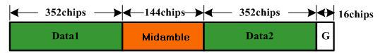
The basic traffic time slot structures are shown below with and without L1 signaling. The modulation type can be either QPSK or 8PSK (2 Mbps). For downlink, the SF (spreading factor) may be 1 or 16. For uplink, the SF may be 1, 2, 4, 8, or 16.
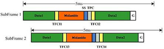
With L1 signaling, the transmission of TPC (transmit power control), SS (synchronization shift), and TFCI (transport format indicator) is done in the data parts of the traffic burst; thus the midamble structure and length are not changed. The graphic below shows the position of each structure in a traffic burst.
The SS field is used to instruct a transmitter to adjust its transmission time.
The TPC field is used for transmission power level adjustment.
The TFCI conveys transport format information to the receiver. The TFCI is distributed into four segments in two five millisecond subframes.
The TPC and SS fields on the physical channel are automatically assigned by the parameter definition of a channel type and its slot format. The TPC is spread with the same spreading factor (SF) and spreading code as the data parts of the respective physical channel.
For each timeslot, data type depends on the channel selection. Available data choices for common physical channels include: PN9 and PN15 sequences, user-defined data, and transport channel data.
For multiframe generation, data is continuous across all packets.
For multicarrier generation, data on each channel is independent.
The midamble is used as a training sequence for channel estimation, power measurements, and synchronization. Up to 16 timeslot midamble codes of length 144 can be generated from a basic midamble code of length 128. (The basic midamble codes are repeated to fill the length.) The actual midamble code transmitted from the midamble field in the time slot depends on the user number and the total number of users allocated the same basic midamble sequence. The midamble used by each user has a unique shift from the basic midamble code, thus providing channel information for different users by one correlation.