Channel pattern can only be set to the subframe (5 ms) level. The configured subframe pattern is repeated. Timeslot #0, (Channel code 1 and 2), is always assigned to P-CCPCH.
Configurable Channels consist of any combination of the following channels listed in the table below.
|
Channel Types |
Description |
|---|---|
|
P-CCPCH |
SF16 x 2 is always assigned on TS #0, Channel Code 1 & 2 |
|
Maximum 1 (SF16) |
|
|
Maximum number is determined by the channel type and the available resource units for both uplink and downlink. |
|
|
Maximum 1 |
|
|
Maximum 1 |
|
|
Maximum 1 |
|
|
Maximum 1 |
|
|
FPACH |
Maximum 1 |
|
Maximum 16 for each timeslot with SF16 Maximum 8 for each timeslot with SF8 |
Consecutive timeslots should be assigned for one channel with the multiple timeslot configuration.

RUs of a multicoded channel can be assigned on any channel code space for each timeslot. Maximum multicode number at a timeslot is 16.

The data (data part, TPC and SS fields) is filled in "Ascending order" of the channel code number (similar to the following figure).

The timing of uplink channels can be changed. Refer to the channel definitions for more details.
All slot formats are supported on a certain RU. Refer to the timeslot formats tables in 3GPP TS25.221 Tables 8F and 8G for a complete list of associated parameters. Slot format is specified to each RU when the channel has a multicode structure.
Timeslot Format Parameters
|
Downlink |
Slot format # 0 to 24 |
|
Uplink |
Slot format # 0 to 69 |
|
Uplink and Downlink (8PSK) |
Slot format # 0 to 24 |
The TFCI, TPC, and SS fields on the physical channel are automatically assigned by the parameter definition of a channel type and its slot format.
The user data of TPC is ordered by the same method as the data part of the multicode/multi timeslot configuration.
|
State |
Off, On Set automatically by the slot format. |
|
TPC field length |
DL (QPSK): 0, 2, 32 UL (QPSK): 0, 2, 4, 8, 16, 32 DL and UL (8PSK): 0, 3, 48 Set automatically by the slot format. |
|
Data |
PN9, PN15, User USER: 512 bits maximum |
|
SS data |
PN9, PN15, User |
|
State |
Off, On Depends on the slot format. Set automatically by the slot format. |
|
TFCI field length (bits) |
DL and UL (QPSK): 0, 4, 8, 16, 32 UL and DL (8PSK): 0, 6, 12, 24, 48 Set automatically by the slot format. |
|
Data |
PN9, PN15, User, Coding (TFCI value) (Initial value = 0) PN9, PN15: (no coding). USER: 512 bits maximum (no coding). Coding:
|
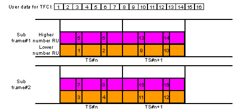
The TFCI data bits of the user file, fill with the numbered order data structure described in the following figure.

If the TFCI user data is shorter than the data required to fill the two TFCI sub-frames, the user data is repeated. The TFCI data fields are filled to the second-sub-frame boundary. After reaching the two-sub-frame boundary, the user data will start again from the beginning to fill the next two subframes. Refer to the figure below.

|
State |
Off, On Depends on the slot format. Set automatically by the slot format. |
|
SS field length |
DL (QPSK): 0, 2, 32 UL (QPSK): 0, 2, 4, 8, 16, 32 DL and UL (8PSK): 0, 3, 48 Set automatically by the slot format. |
|
Data |
PN9, PN15, USER (Initial = "01") USER: 512 bits maximum. |
A user data of SS is ordered using the same method as the data portion of the multicode/multi timeslot configuration.
Any slot format combination is possible.
TFCI, TPC, SS of each RU runs independently of the other RUs.
The payload of the physical layer uses a user file repeatedly until the total data size reaches a certain payload size. The payload size is channel dependent. Refer to the specific channel definition for more information.
Code allocation depends on the code group of the carrier:
SYNC-UL ID : [SYNC-DL ID * 8 --- SYNC-DL ID * 8 + 7]
Midamble code: [SYNC-DL ID * 4 --- SYNC-DL ID * 4 + 3]
Scrambling code: [SYNC-DL ID * 4 --- SYNC-DL ID * 4 + 3]
Basic midamble code and scrambling code are always the same.