Power Settings
Power Calculation
| Channel
Power Assignment | RU and Timeslot
Power Assignment
Power Calculation
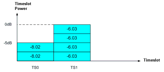
Multi-Timeslot
The channel power on each timeslot is the same.
Multicode
When multiple RUs are assigned for each channel,
the power ratio of each RU on the multicode configuration is related to
the SF of each RU. For example, two RUs (referred to here as RU1 and RU2)
are assigned to a channel. Each RU has its own SF. For this configuration,
the following is true:
RU1 power : RU2 power = SF of RU2 : SF of RU1
Midamble
The summed power balance between midambles and the
data parts should be the same in each timeslot. If the same midamble is
assigned to multiple RUs, the total midamble power is set to 1/n
to maintain the power balance within each of the data parts.
Channel Power Assignment
-
The system assigns channel power based on 0 dB in the
UI.
-
Actual power level is set in dBm on the signal generator.
The maximum power which is set in the UI is mapped to the signal generator
power level with the ALC ON.
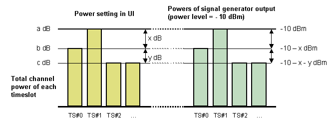
-
For multiple channels that are in the same timeslot
and/or have AWGN power applied, the power is additive.
The total power value of a timeslot may be exceeded at 0 dB.
For example: If 2 channels, 0 dB channel
and 0 dB channel, are combined in the same timeslot, the final power becomes
3 dB. If 3 dB is the maximum power of the power configuration, this 3
dB will be mapped to a signal generator power level. To avoid an over
range error, each assigned channel power needs to be recalculated relatively,
from 3 dB and the signal generator power level.
The following figure illustrates the power
mapping from the UI power setting to the signal generator power output
level.
RU and Timeslot Power Assignment
In the basic carrier setup, you can set the RU power relative to the
value of the other RUs. Timeslot power is equal to the sum of all the
RU powers and can be adjusted relative to the other timeslots as needed.
For example: