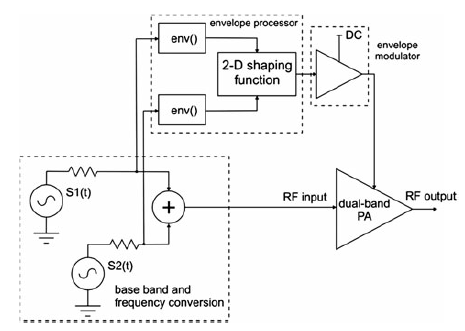
To understand envelope tracking on dual band PA testing application, it’s essential to understand the basic envelope tracking concept which firstly introduced in signal band PA testing application. Like single band ET (envelope tracking) technology used in single band PA application, dual band ET is used in dual band application to improve the efficiency of PA. That means concurrent dual-band transmission requires the ETPS to be capable of tracking the envelope of the dual-band signal including low-frequency components (in the order of modulation bandwidth for each band) as well as high-frequency components (in the order of frequency separation between the two bands). Since the frequency spacing may be in the orders of hundreds of megahertz, it is impractical for the envelope amplifier to follow the original envelope of the dual-band signal. So normally only the low frequency components of the envelope of the dual-band signal is used to modulate the drain supply of the PA (like below graph).
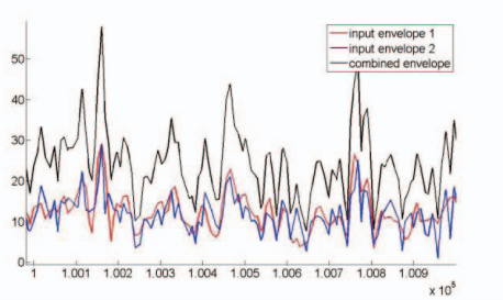
Normally meaningful ETPS out waveform is created based on the waveform carried by the RF signal which drivers the PA, so here one internal technique which called 2D Supply Modulation Technique is provided to create the combined envelope, E1 and E2 is the absolute RF envelope voltage which has been scaled based on actual RF power. (See equation below.)
2D Supply Modulation Technique: combined envelope = (|E1|+|E2|) x shaping(E)
From the concept point of view the key difference of dual band ET compared with single band ET is the creation of combined envelope, because envelope combination technique is based on the alignment of band 1 signal and band 2 signal, so like single band application, before applying envelope tracking, RF 1 and RF 2 signal should be aligned firstly, then align them with the ETPS output. RF signal of 2 bands and ETPS output must be aligned strictly in time, otherwise DPD action cannot get the result we expected.