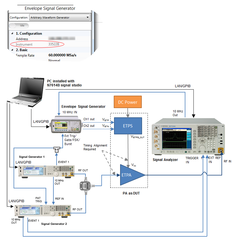
The following figures show the instrument connection for a dual-band envelope tracking measurement. ![]() Figure 1 shows the measurement setup when 33522B/33622A AWG is used as envelope signal generator.
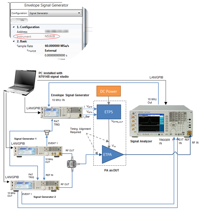
Figure 1 shows the measurement setup when 33522B/33622A AWG is used as envelope signal generator. ![]() Figure 2 shows the measurement setup when N5172B EXG/N5182B MXG is used as envelope signal generator.
Figure 2 shows the measurement setup when N5172B EXG/N5182B MXG is used as envelope signal generator.
In the system connection diagrams above, the dark blue lines are for RF connection; the light blue lines are for reference, trigger, and envelope signal connection; the black lines are for instrument control connection with LAN or GPIB. In envelope tracking test, timing alignment is required between the ETPA Vcc input and the RF input signal.
The table below shows the supported instruments for envelope tracking measurement. For details about the options required for each instrument model, refer to System Requirements.
| Instrument Type | Instrument Model Supported |
|---|---|
|
RF Signal Generator 11 |
N5182B MXG |
|
RF Signal Generator 21 |
N5182A MXG N5182B MXG |
|
Envelope Signal Generator |
33522B Arbitrary Waveform Generator 33622A Arbitrary Waveform Generator N5182B MXG N5172B EXG |
To set up the measurement system, follow the steps below:
Connect the PC installed with N7614C Signal Studio to the RF Signal Generator, Envelope Signal Generator, and Signal Analyzer through LAN or GPIB.
Connect the 10MHz reference signal of system which follow the order of 10MHz reference out of RF signal generator 1->REF In Port of RF signal generator 2; 10MHz reference out of RF signal generator 2->EXT REF IN port of signal analyzer; 10MHz out port of signal analyzer ->10MHz in of envelope signal generator.
If when N5172B EXG/N5182B MXG is used as the envelope signal generator, then connect the Event 1 port out of RF signal generator 1 to PAT Trigger port of RF signal generator 2 and envelope generator simultaneously via one power divider; if 33522B/33622A is used as the envelope signal generator, then connect the Event 1 port out of RF signal generator 1 is connect to PAT Trigger port of RF signal generator 2, and simultaneously connected to the EXT Trig port of envelope signal generator.
If N5172B/N5182B is used as Envelope Signal Generator, connect the I OUT and OUT of the Envelope Signal Generator to the VETP and VETN port of the ETPS and connect the VETPS_OUT port of the ETPS to the Vcc of the ETPA; If 33522B or 33622A is used as Envelope Signal Generator, connect the Channel 1 and Channel 2 output of the Envelope Signal Generator to the VETP and VETN port of the ETPS and connect the VETPS_OUT port of the ETPS to the Vcc of the ETPA.
Connect the output of 2 RF signal generators to PA input and PA output to signal analyzer which is same in dual-DPD application.