Open topic with navigation
3. Executing the Measurement and Viewing Results
This section introduce how to execute the envelope tracking test and how to view the measurement results. Follow the procedure below to execute the measurement and view the measurement results.
Initial Run
Timing Alignment
Executing the Measurement
Viewing the Measurement Results
Initial Run
-
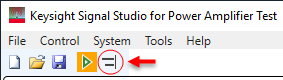
Click the  Run button on the tool bar to get the RF and ET waveform downloaded into the instrument and get the initial measurement results.
-
Once the measurement begins, the detailed information will be displayed in the Log view at the bottom of the window as shown below.
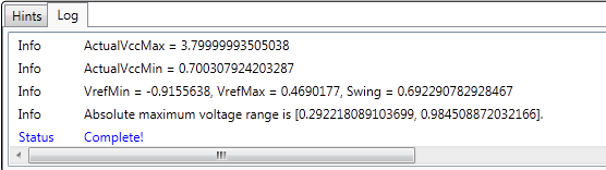
During the running process, you can stop it any time by clicking the Stop button. When you see the "Complete!" message in the Log view, it indicates that the measurement is completed.
The default Delay setting in Envelope Tracking block may not be the optimal value for the current instruments/DUT connections. So the PA output performance (AM-AM, ACP) may be poor. Further timing alignment between the RF Signal Generator and the Envelope Signal Generator is required.
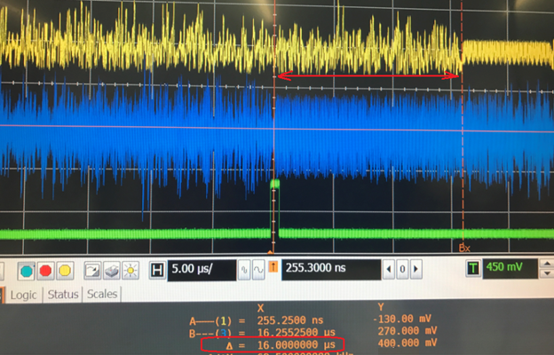
Timing Alignment
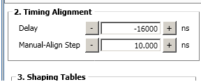
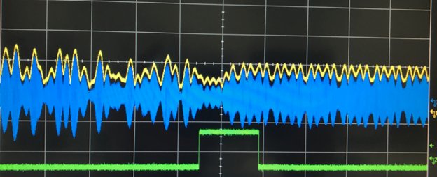
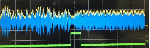
Timing alignment is to synchronize the input signal of the PA (the output of the RF Signal Generator) with the input voltage of the PA (the output of the Envelope Signal Generator) in time domain. There are two methods:
Once sample rate related setting changed, or M8190 was reset manually, the relative timing between envelope signal and RF signal signal will become unknown and unstable, “run” action and “align” action must be repeat again.
If the related settings (e.g. sample rate, IQ delay, trigger delay in Generator instruments, etc.) are changed and applied, it is recommended to do the timing alignment again.
Executing the Measurement
Once a proper time alignment has completed, the signal can be played repeatedly without re-alignment. Click the Run button to play the signal and get the measurement results.
Viewing the Measurement Results
In the measurement view, there are four result windows: AM-AM, AM-PM, ACP, and EVM vs. Power. EVM vs. Power results are displayed only when Power Sweeping (in PA block) is set to On.
For ET test, ACP results are viewed. To view more detailed information, double-click on the ACP window to enlarge it as shown in the figure below.
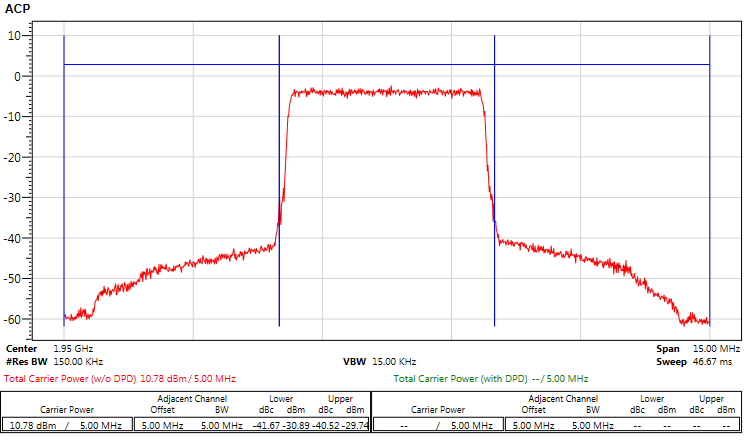
Figure 1. ACP Results
You can make your own measurements, such as power-added efficiency (PAE) test, based on the PA output signal using the Signal Studio for Power Amplifier Test software, Keysight VSA software or applications on the Signal Analyzer. For information on how to make PAE measurements, see Example PAE Measurements.
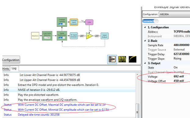
Depending on the test scenario, the envelope signal output for M8190A can vary. However, the M8190A output amplitude varies with the offset value, so it is important to pay attention and check if the M8190A (envelope signal generator) output has been clipped.
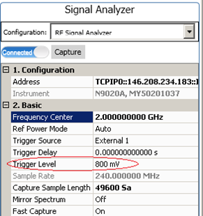
If the signal analyzer fails to wait for triggering, there can be two possible reasons:
-
The trigger signal cable may not be well connected;
-
The trigger level is not appropriate because of the possible BNC divider used in the system connection
In both the cases, the trigger level adjustment is needed.