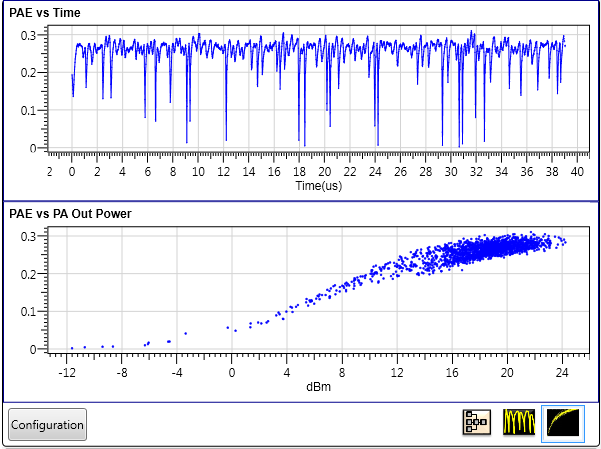
PAE Measurement View shows the PAE measurement results of the PA test. Two result windows are provided: PAE vs Time and PAE vs PA Out Power. Double-click each result window to enlarge it to see more detailed information and then double-click again to return to the default layout.
PAE vs Time result windows displays the PAE result against time.
PAE vs PA Out Power result window shows the statistical distribution of PAE result. It helps to find the input or output levels at which the DUT works most efficiently.
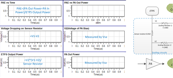
PAE is calculated using the following formulas:
Voltage Dropping on Sensor Resistor = V1-V2
ETPS Output Power = V2*(V1-V2)/(Sensor Resistor)
If Intermediate results is in “Off” state, then only PAE vs Time and PAE vs PA Out Power results are visible.

This button connects to the instrument after entering the its Address in the Configuration property grid. It also displays the following status conditions:
Idle: No instrument is connected.
Connecting: The software is in the process of connecting to the instrument.
Connected: The software is connected to the instrument.
|
1. Configuration |
2. Basic |
3. Advanced |
4. V1/V2 External Scaling | 5. Current Sensoring |
|---|---|---|---|---|
|
Measurement Channel 1 Impedance |
|
Enter the instrument address.
The drop down list of Address lists the recently used instrument address and the connection strings (GPIB, USB, LAN, etc.) configured in the IO Connection Expert.
Default: I
This parameter displays the model number and serial number of the instrument if the status of Instrument Connection Button is Connected.
Default: I
Define the BBA port used for measuring V1 scaling out of scaling circuits. V1 is the voltage signal at the entry point of the sensor resistor.
Default: 50Ω
Choice: 50Ω|1MΩ
Define the input impedance of measurement channel 1.
Default: I̅ (I_Bar)
Choice: I̅ | Q
Define the BBA port used for measuring V2 scaling out of scaling circuits. V2 is the voltage signal at the exit point of the sensor resistor.
Default: 50Ω
Choice: 50Ω|1MΩ
Define the input impedance of measurement channel 2.
Range: Determined by the instrument models and options.
Default: The value should not be less than the waveform sample rate.
Coupling: Available choices are coupled with the internal sample clock and baseband sample rate.
Gets or sets the RF carrier frequency of PA output in Hertz.
Range: 1 MHz to Sample rate determined by the instrument models and options.
Default: 5 MHz
Coupling: It has default sample rate same as the sample clock of envelope signal generator,
Indicates the sample rate used to sample the ETPS output waveform,
Default: External1
Choice:External 1
Coupling: Read only, External 1 is the only choice.
Sets the Trigger Source.
Choice: Determined by the instrument models and options.
Default: 0 sec
Gets or sets the Signal Analyzer Trigger Delay.
Range: 20us to 500us
Default: 20us
Set time duration of data including the ETPS output and RF signal will be captured for PAE measurement.
Choice: On | Off
Default: Off
Coupling: When the value is On, six result traces are displayed. Otherwise only two traces (PAE vs Time, PAE vs PA Out Power) are displayed.
Choose whether to display the intermediate results or not.
Range: 1 to 20
Default: 5
Set the ratio of V1/BBA measurement value
Gain of V1 Scaling=(BBA Input Impedance 1+Scaling Resistor 1)/(BBA Input Impedance 1)
Gain of V2 Scaling=(BBA Input Impedance 2+Scaling Resistor 2)/(BBA Input Impedance 2)
Generally,
Scaling Resistor 1= Scaling Resistor 1
BBA Input Impedance 1= BBA Input Impedance 2
Range: 0 to 20
Default: 0
Compensate the offset value when V1=0 or V2=0. Generally, V1=0. For example, the BBA measurement should be zero after BBA calibration. If not, it can be used as compensation, but generally after BBA calibration, this value should be zero as default.
Range: 0.01Ω to 100Ω
Default: 0.05Ω
Value of sensor resistor, used in current calculation based on voltage dropping.