This block provides ![]() parameters for adding some basic processing to the original I/Q waveform file prior to further CFR/DPD/ET processing.
parameters for adding some basic processing to the original I/Q waveform file prior to further CFR/DPD/ET processing.

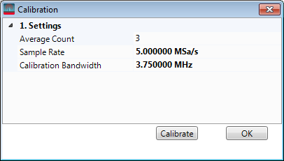
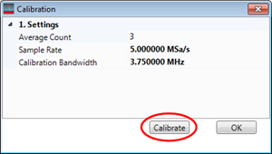
Opens a ![]() Calibration window where you can configure and then run the calibration algorithm.
Calibration window where you can configure and then run the calibration algorithm.
Average Count – Specifies the average count of the calibration. Default: 3. Range: 3 to 10.
Sample Rate – Specifies the calibration sample rate. The sample rate should be the same as the waveform sample rate after resampling. Default:1 GHz. Range: 5 MHz to 10 GHz.
Calibration Bandwidth – Specifies the calibration bandwidth. This value should be less than the sample rate. Default: 800 MHz. Range: 5 MHz to 10 GHz.
Calibrate – Runs and saves the correction filter coefficients to a file.
See also Correction Filter and Correction Filter File.

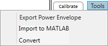
Opens a ![]() drop-down menu with the following tools. Available tool selections are dependent upon the selected Waveform Type (see table below).
drop-down menu with the following tools. Available tool selections are dependent upon the selected Waveform Type (see table below).
Waveform Type settings required to activate various Tools selections
|
Waveform Type |
Export Power Envelope |
Import to MATLAB |
Convert |
|---|---|---|---|
|
Preloaded |
Active |
Inactive |
Inactive |
|
Signal Studio |
Active |
Inactive |
Inactive |
|
User-defined |
Inactive |
Active |
Active |
|
MATLAB Variable |
Inactive |
Inactive |
Active |
Export Power Envelope – Exports the power envelope of a Signal Studio waveform. See also Exporting the Power Envelope.
Import to MATLAB – Imports the selected I/Q waveform file into a MATLAB workspace.
Convert – Converts the selected I/Q file into one of these other file formats: .txt, .csv, .bin (16-bit big endian), or .mat.
|
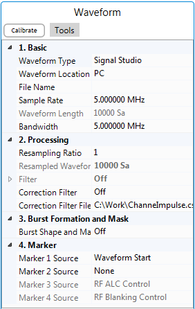
1. Basic |
2. Processing |
3. Burst Formation and Mask |
4. Markers |
|---|---|---|---|
Choice: Preloaded | Signal Studio | User-defined | MATLAB Variable
Default: Signal Studio
Specify the type of waveform. It has three different choices, Preloaded, Signal Studio and User-defined.
Preloaded – N7614C Signal Studio for Power Amplifier Test 2022 provides about 20 waveforms that do not require waveform licenses to use. These include WLAN, LTE, and 5GNR waveforms with various settings.
Signal Studio – Select this option to use the waveform generated with another Keysight Signal Studio.
To use the waveform generated by another signal studio, the RF Signal Generator needs to have the corresponding license. For this example, if you plan to use the LTE waveform exported by N7624B signal studio, you need to have the N7624B license.
User-defined – Select this option to use a waveform in a certain format generated by the user.
MATLAB Variable – Select this option to use a waveform from the MATLAB workspace. See also IQ Variable Name.
Choice: PC | RF Signal Generator
Default: PC
Coupling: This cell is grayed out if the waveform type is set to Preloaded or User-defined or when the RF Signal Generator Configuration is set to AWG + Signal Generator.
Select the waveform location for a signal studio waveform.
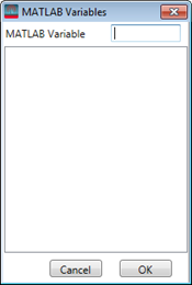
When MATLAB Variable is selected as the Waveform Type, clicking this parameter opens a ![]() window where you can choose an I/Q variable name from the MATLAB workspace. The I/Q variable should be a 1-d complex array. If you have a valid license, you can launch MATLAB from the Signal Studio software's System menu and then use this window to browse or directly input a variable.
window where you can choose an I/Q variable name from the MATLAB workspace. The I/Q variable should be a 1-d complex array. If you have a valid license, you can launch MATLAB from the Signal Studio software's System menu and then use this window to browse or directly input a variable.
Choice: CSV/Text | Big Endian 16 Bits | MATLAB
Default: CSV/Text
Coupling: Available when the Waveform Type is set to User-defined.
Specify the format of the source file when the Waveform Type is set to User-defined.
CSV/Text – .csv or .txt format: I/Q data is interleaved and delimited with commas. Example: 1.235,-3.123.
Big Endian 16 Bits – This is for unencrypted MXG/EXG waveforms. It is I/Q DAC bit value and the leftmost bit is MSB. I and Q are interleaved.
MATLAB – .mat format: This is for Matlab waveforms. If the .mat file contains several complex arrays, only the first array will be imported as the waveform.
Click the  in the right side of the cell to browse the computer and select the waveform file.
Range: 1 MHz to 8 GHz
Default: 5 MHz
Coupling: This cell is read-only when the Waveform Type is set to Predefined or Signal Studio.
It indicates the sample rate used by the waveform when Waveform Type is set to Predefined or Signal Studio. Sample rate is extracted from the header file of the waveform. You need to specify the sample rate manually when the Waveform Type is set to User-defined.
Waveform Length is read-only and it indicates the sample number in the waveform.
Range: 1 to 200 MHz
Default: 5 MHz
Specify the bandwidth of the waveform.
Range: 0.1 to 20
Default: 1
Coupling: The resultant sampling rate will not be greater than 200 MHz if the configuration is set to RF Signal Generator (MXG-B). The resampling ratio is displayed as a fraction after rational approximation. You should set a proper resampling ratio to make the resampled waveform cyclic, that is, the waveform length should be able to be divided by the decimator. The software doesn’t do extra coupling to make sure the waveform is cyclic, instead, it reports an error after you click Run when the waveform length cannot be divided by the decimator.
Specifies the resampling ratio (RSR) that up-samples the waveform. This is not the RSR used by the imported waveform. Rather, it is the RSR that the software uses to resample the waveform. It is expected that the signal employed to extract a DPD model should have a resampling rate no less than 3. If the selected waveform's up-sampling ratio is less, it can be up-sampled here with a resampling ratio greater than 3. If the user-defined or chosen waveform file already has a high over-sampling ratio beyond the capability of the selected signal generator, then the created waveform must be be resampled with a ratio less than 1.
Range: 1 to Int32.Max
Default: 10000
Coupling: It equals the product of Waveform Length and Resampling Ratio.
It indicates the sample number of the waveform after resampling.
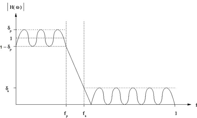
Set the parameters to design a Parks-McClellan low pass filter in the menu below. The Parks-McClellan design method uses the Remez exchange algorithm to design linear phase FIR filters such that a filter has minimum weighted Chebyshev error in approximating a desired ideal frequency response. For more details, refer to Chapter 7.4.3 in "The Parks-McClellan Algorithm in Discrete-Time Signal Processing, 2nd ed".
The filter can be depicted as below, in which
fp is the pass frequency,
fs is the stop frequency,
δp is the pass ripple,
δs is the stop ripple.
Choice: On | Off
Default: Off
Double-click or use the drop-down menu to enable or disable the application of the filter.
Range: 1 to 2048
Default: 300
Set the maximum filter length. The filter’s length is clipped to the Maximum Order if the minimum filter length required to satisfy its specification exceeds the Maximum Order.
Range: 1 Hz to (Stop Frequency - 0.0015*Sample Rate*Resampling Ratio in Waveform block/2)
Default: 1.25 MHz
Set the pass frequency of the filter.
Range: 2 Hz to (0.5*Sample Rate*Resampling Ratio)
Default: 1.5625 MHz
Set the stop frequency of the filter.
Range: 0.0001 to 5.0
Default: 0.01
Set the maximum ripple in the pass band.
Range: 6.0 to 200.0
Default: 50.0
Set the maximum ripple in the stop band.
Choice: On | Off
Default: Off
This value indicates whether the correction filter will be applied when you run the test flow.
See also Calibrate Button and Correction Filter File.
Default: C:\Work\ChannelResponse.csv
Specifies the correction filter file name. When you click the ![]() Calibrate button the correction filter coefficients are saved to this file. When Correction Filter is on, the filter coefficients will be read from the file and used in the test flow.
Calibrate button the correction filter coefficients are saved to this file. When Correction Filter is on, the filter coefficients will be read from the file and used in the test flow.
See also Calibrate Button.
Choice: On | Off
Default: Off
Coupling: Its state is mutually exclusive with the state of Envelope Tracking. They can’t be set to On at the same time.
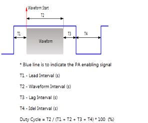
Enable or disable the construction of burst by adding intervals to the waveform and generating of a PA enabling mask signal. When it is set to on, intervals will be added prior to and after the waveform to achieve a certain duty cycle. In the meantime, a mask signal is generated according to the specified time intervals.
Range: 1% to 100%
Coupling: Available when Burst Shape & Mask is set to On. Its value is equal to T2/(T1+T2+T3+T4)*100%.
It indicates the Duty Cycle of the burst.
Range: 0 to 100 μs
Default: 1 μs
Coupling: Available when Burst Shape & Mask is set to On. It should be less than T4.
Specifies the time interval ahead of waveform.
Range: 1 μs to 10 s
Default: 2 ms
Coupling: Available when Burst Shape & Mask is set to On. It equals to the quotient of the Waveform Length and the Sample Rate.
It indicates the time length of the waveform.
Range: 0 to 10 μs
Default: 1 μs
Coupling: Available when Burst Shape & Mask is set to On.
Specify the time interval after waveform.
Range: 0 to 60 s
Default: 1 ms
Coupling: Available when Burst Shape & Mask is set to On.
Specifies the length of the idle interval added to the waveform.
Configure the marker points for Marker 1 using the Marker Source Selection dialog box.
The signal generator outputs the Marker 1 signal from the rear-panel EVENT 1 output. For more information, see the signal generator's User Guide.
Configure the marker points for Marker 2 using the Marker Source Selection dialog box.
The signal generator outputs the Marker 2 signal from the rear-panel EVENT 2 output. For more information, see the signal generator's User Guide.
This parameter is read-only and it indicates Marker 3 is used to control ALC hold.
The signal generator outputs the Marker 3 signal from the rear-panel EVENT 3 output. For more information, see the signal generator's User Guide.
This parameter is read-only and it indicates Marker 4 is used to control Pulse/RF Blank.
The signal generator outputs the Marker 4 signal from the rear-panel EVENT 4 output. For more information, see the signal generator's User Guide.