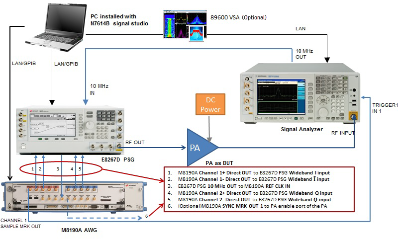
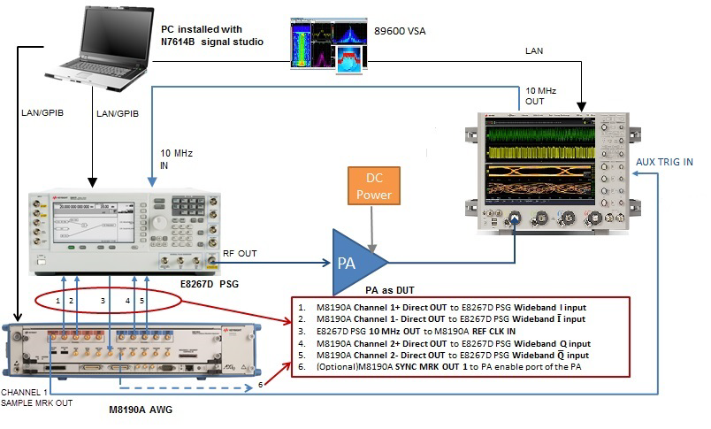
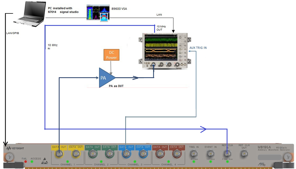
The following figures show the instrument connections for a wideband DPD measurement.
In the system connection diagram above, the dark blue lines are for RF connection; the light blue lines are for reference and trigger connection; the black lines are for instrument control connection with LAN.
The table shows the requirement for the instruments used in DPD measurement. For details about the options required for each instrument model, refer to System Requirements.
|
Instrument Type |
Instrument Model Supported |
|---|---|
|
RF Signal Generator |
M8190A AWG (Arbitrary Waveform Generator) + E8267D PSG Vector Signal Generator 1 |
|
Signal Analyzer |
N9030A/B PXA N9040B UXA |
|
Oscilloscope |
Keysight scope models compatible with 89600 VSA |
1. This configuration is used for wideband DPD support, in which M8190A works as IQ waveform generator and E8267D PSG works as modulator & up converter.
To set up the measurement system, follow the steps below:
Connect the PC installed with N7614C Signal Studio and 89600 VSA software to M8190A AWG, E8267D PSG, and signal analyzer (or oscilloscope) through LAN.
Connect the CHANNEL 1 SAMPLE MRK OUT port of M8190A AWG to the Trigger IN 1 port on the rear panel of the signal analyzer (or AUX TRIG IN of the oscilloscope) using a BNC cable. If the high bandwidth channel is used for UXA H1G, the trigger source should be set to external 3.
Connect the 10 MHz OUT port on the rear panel of the signal analyzer to the 10 MHz IN port on the rear panel of the E8267D PSG using a BNC cable.
Connect IQ baseband signal from M8190A AWG to the external IQ input port of E8267D PSG:
Connect M8190A Channel 1+ Direct OUT port to E8267D PSG Wideband I input port
Connect M8190A Channel 1- Direct OUT port to E8267D PSG Wideband I̅ input port
Connect M8190A Channel 2+ Direct OUT port to E8267D PSG Wideband Q input port
Connect M8190A Channel 2- Direct OUT port to E8267D PSG Wideband Q̅ input port
The four cables used for I, I̅, Q, and Q̅ signal connections should have the same characteristics.
Connect the 10 MHz OUT port of E8267D PSG to the REF CLK IN port of M8190A AWG.
Connect the RF OUTPUT port of the E8267D PSG to the RF INPUT port of the signal analyzer (or channel 1 of the oscilloscope) for calibration.