
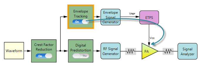
Voltage Mapping is an important concept and digital process in envelope tracking measurement, involving parameters in several blocks. This section illustrates the detailed relationships in the related parameters. Most of the envelope tracking algorithm and terminology used in this section is compliant to MIPI eTrak spec.
Voltage mapping involves three blocks:
Envelope Tracking block
In this block, shaping table is specified. Shaping table defines the relationship between input column (RF Voltage) and the supply voltage of the PA (Vcc). The input column can be Normalized I/Q Amplitude, Absolute RF Output Voltage of the input signal or Override Absolute RF.
Envelope Signal Generator block
In this block, Voltage is calculated through voltage mapping process and Voltage Offset is also set in the process.
If the Envelope Signal Generator in use is N5172B EXG or N5172B MXG, another setting Peak Voltage will be calculated instead of Voltage.
ETPS
In this block, two parameters for the PA are set: ETPS Gain and Vcc Offset and one parameter defined in MIPI eTrak spec is set: VCM.
To introduce voltage mapping, two sections are included:
Voltage Mapping Procedure in N7614C
Equation 1 shows the relationships of the related parameters, which is from eTrak spec.


where,
Vcc is the supply voltage of the PA, which is also called VETPS_OUT in eTrak spec.
Vcc_offset is the Vcc Offset parameter in ETPS block. This parameter can be measured at the ETPS output by setting VREF to 0.
ETPSGAIN is the amplification of the differential supply voltage, which corresponds to ETPS Gain setting in ETPS block.
VETP is the positive signal output of the Envelope Signal Generator.
VETN is the negative signal output of the Envelope Signal Generator.
VREF is used as the reference for ETPS.
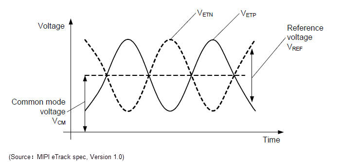
VCM is the common mode voltage as defined in MIPI eTrak spec.
The following figure illustrates the relationship between VETP, VETN, VREF, and VCM clearly.
In N7614C Signal Studio for Power Amplifier Test 2022, voltage mapping works as follows:
Use the shaping table defined in Envelope Tracking block to calculate the supply voltage of PA (Vcc) from the RF voltage of the signal.
Calculate VREF using a transformation of equation 1 as shown in equation 2. Note that VCC_offset and ETPSGAIN values are set in ETPS block.

Calculate the single port Voltage value for Envelope Signal Generator block using equation 3.

in which VREF_MAX is the maximum value of VREF, VREF_MIN is the minimum value of VREF.
The Voltage Offset value in Envelope Signal Generator block is equal to the VCM value in ETPS block. VCM parameter is independent from the parameters discussed above and can be set by the user as required.
If the Envelope Signal Generator in use is N5172B EXG or N5172B MXG, another setting Peak Voltage will be used instead of Voltage.
