This block controls the DPD processing for the IQ waveform. You can turn on digital predistortion or set it Thr (through) by clicking the  toggle button on the block.
toggle button on the block.toggle button on the block.The Digital Predistortion block supports two DPD modes. Each mode has a unique set of parameters.
Extract and Apply: First, the PA model is extracted using the algorithm and parameters set in this block and PA output signal from the Signal Analyzer. Then the waveform is pre-distorted based on the extracted model to compensate for the non-linearity introduced by the PA.
Apply Only: The waveform is directly pre-distorted with the user input LUT of PA input versus PA output in terms of amplitude and phase or the Memory Polynomial or Volterra Series Coefficient File.
 block.png)

Click this button to export the DPD model into a .csv file.This button is only visible when the DPD Mode is set to Extract and Apply.
If the PA Model Type is Look-up Table, the exported .csv file has three rows, which are AM In (V), AM Out (V), and PM Out (deg) respectively. The exported coefficients of the DPD model can be applied to the IQ data when DPD Mode is set to Apply IQ LUT.
If the PA Model Type is Memory Polynomial or Volterra Series, the exported .csv file has one row which is the coefficient of the polynomial that is used for DPD modeling.The exported data can not be applied to the IQ data through N7614B Signal Studio for Power Amplifier Test.

Click this button to export the pre-distorted waveform to a file. The waveform is encrypted and can be played on a signal generator with the related licenses. Note that no file will be exported if the current Mode is Real-time or the Digital Predistortion block is set to off.
|
1. General |
2. Model Settings |
3. Details |
|---|---|---|
|
MATLAB Script |
||
|
1. Function 2. Input Variables 3. Output Variables |
Choice: Extract and Apply | Apply Only
Default: Extract and Apply
Double-click or use the drop-down menu to set the DPD mode.
Choice: On | Off
Default: Off
Coupling: Disables Burst Shape and Mask in Waveform block
This parameter activates carrier frequency offset compensation. It should be used when one of the 10 MHz reference is not connected.
When you use an AXIe AWG configuration without PSG, the DUT accepts the I/Q signal from M8190A. The I/Q modulation, up-conversion and PA are integrated together. If there is no 10 MHz external reference on the DUT, the RF signal may have a carrier frequency offset when the signal analyzer captures the I/Q data. So frequency offset compensation should be used.
Before playing a waveform, extract DPD model or apply DPD, a training signal will be sent first, and the signal will be captured. The frequency offset will be estimated based on the captured signal.
Range: 1 to 1000
Default: 1
Enter the iteration number for the DPD process.
Choice: Memory Polynomial | Volterra Series | Look-up Table | User-defined MATLAB Script
Default: Look-up Table
Double-click or use the drop-down menu to select the PA model extraction algorithm to be used. Memory Polynomial is a simplified version of Volterra Series. Look-up Table is suitable for memoryless PA component.
When PA Model Type is set to User-defined MATLAB Script (supported only under ARB and Extract and Apply modes), the N7614B software interacts with MATLAB to execute the DPD algorithm defined in the MATLAB script. The N7614B software also controls the instruments to run the whole test flow.
If User-defined MATLAB Script is selected, Signal Studio and Preloaded become invalid selections for Waveform Type.
For more detailed information, refer to DPD Concept.
Choice: LSE using QR | LSE using SVD
Default: LSE using QR
Coupling: Available only when the DPD Mode is set to Extract and Apply and the PA Model Type is set to Memory Polynomial or Volterra Series.
Double-click or use the drop-down menu to specify the model identification algorithm.
Range: 0 to 20
Default: 1
Coupling: Available only when the DPD Mode is set to Extract and Apply and the PA Model Type is set to Memory Polynomial or Volterra Series.
Set the memory depth of the DPD model.
Range: 1 to 20
Default: 5
Coupling: Available only when the DPD Mode is set to Extract and Apply and the PA Model Type is set to Memory Polynomial or Volterra Series.
Set the nonlinear order of the DPD model.
Range: 0 to 10
Default: 0
Coupling: Available only when the DPD Mode is set to Extract and Apply and the PA Model Type is set to Volterra Series.
Set the order of the cross terms in the Volterra Series algorithm.
Choice: On | Off
Default: Off
Coupling: Available only when the DPD Mode is set to Extract and Apply and the PA Model Type is set to Memory Polynomial or Volterra Series.
Double-click or use the drop-down menu to specify whether to use only the odd orders of the nonlinear terms or not.
Choice: Normalized | Absolute
Default: Normalized
Coupling: Available only when the PA Model Type is set to Look-up Table.
Set the type of values in the AM/AM, AM/PM in the look-up table.
Range: 1 to 3000
Default: 128
Coupling: Available only when the DPD Mode is set to Extract and Apply and the PA Model Type is set to Look-up Table.
Set the size of the look-up table. The amplitude range of the PA input signal is divided into equal parts with the number of LUT Size. And each segment is an entry for look-up table.
Range: 1 to 12
Default: 5
Coupling: Available only when the DPD Mode is set to Extract and Apply and the PA Model Type is set to Look-up Table.
Enter the order for the polynomial approximation of the AM/AM curve.
Range: 1 to 12
Default: 5
Coupling: Available only when the DPD Mode is set to Extract and Apply and the PA Model Type is set to Look-up Table.
Enter the order for the polynomial approximation of the AM/PM curve.
Set the MATLAB script command line. The software will invoke this function via MATLAB API. Assume the script file is under MATLAB working path. The function name (e.g. dpd) should be the same with the MATLAB function name, the input variable name (e.g. dpdIn, dutIn, capture) and output variable name (eg. dpdOut) should match the software settings under Digital Predistortion block.
Default: dpdIn
Set the variable name for normalized DPD input waveform. The waveform is the baseband I/Q waveform without DPD. The waveform is normalized to 1 with its peak magnitude. User’s MATLAB script will apply the extracted DPD model on the DPD input waveform and get the predistorted baseband waveform. For the first iteration, the Normalized DPD input waveform should be the same as the Normalized PA Input.
Default: dutIn
Set the variable name for normalized PA Input waveform. User will use Normalized PA Input waveform and Captured waveform to extract the PA model. If user need absolute PA input waveform, user should calculate the waveform based on Normalized PA Input, Signal Generator Power, and Loss In.
Default: captured
Set the variable name for captured waveform. User will use Normalized PA Input waveform and Captured waveform to extract the PA model. If user need absolute PA output waveform, user should calculate the waveform based on Captured and Loss Out.
Default: sgPower
Set the variable name for Signal Generator power. The variable value will be the Amplitude value under RF Signal Generator block and it will be written into MATLAB workspace.
Default: lossIn
Set the variable name for loss in. The variable value Loss In value under PA block and it will be written into MATLAB workspace.
Default: lossOut
Set the variable name for loss out. The variable value Loss Out value under PA block and it will be written into MATLAB workspace.
Default: dpdOut
Set the variable name for predistorted waveform.
Click this button to export the pre-distorted waveform to a file. The waveform is encrypted and can be played on a signal generator with the related licenses. Note that no file will be exported if the current Mode is Real-time or the Digital Predistortion block is set to off.
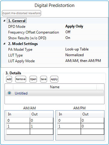
| 1. General | 2. Model Settings | 3. Details |
|---|---|---|
Choice: Extract and Apply | Apply Only
Default: Extract and Apply
Double-click or use the drop-down menu to set the DPD mode.
Choice: On | Off
Default: Off
Coupling: Disables Burst Shape and Mask in Waveform block
This parameter activates carrier frequency offset compensation. It should be used when one of the 10 MHz reference is not connected.
When you use an AXIe AWG configuration without PSG, the DUT accepts the I/Q signal from M8190A. The I/Q modulation, up-conversion and PA are integrated together. If there is no 10 MHz external reference on the DUT, the RF signal may have a carrier frequency offset when the signal analyzer captures the I/Q data. So frequency offset compensation should be used.
Before playing a waveform, extract DPD model or apply DPD, a training signal will be sent first, and the signal will be captured. The frequency offset will be estimated based on the captured signal.
Choice: On | Off
Default: On
Coupling: Available only when DPD Mode is set to Apply IQ LUT and Measurement Enabled in the Measurement view settings is set to On.
Double-click or use the drop-down menu to choose whether to make AM-AM, AM-PM,and ACP measurements without applying DPD, for comparison.
If this parameter is set to On, in the measurement view, AM-AM, AM-PM, ACP windows will display two measurement traces, with DPD and without DPD.
If this parameter is set to Off, in the measurement view, AM-AM, AM-PM, ACP windows will display only one measurement trace, with DPD.
Choice: Memory Polynomial | Volterra Series | Look-up Table
Default: Look-up Table
Double-click or use the drop-down menu to select the PA model extraction algorithm to be used. Memory Polynomial is a simplified version of Volterra Series. Look-up Table is suitable for memoryless PA component.
For more detailed information, refer to DPD Concept.
Choice: Normalized | Absolute
Default: Normalized
Coupling: Available only when the PA Model Type is set to Look-up Table.
Set the type of values in the AM/AM, AM/PM in the look-up table.
Choice: AM/AM, then AM/PM | AM/PM, then AM/AM | AM/AM Only | AM/PM Only
Default: AM/AM, then AM/PM
Coupling: Available only when the PA Model Type is set to Memory Polynomial or Volterra Series.
Set the method to apply the LUT table. Refer to Digital Pre-distortion Concept for more details.
Coupling: Available only when the PA Model Type is set to Memory Polynomial or Volterra Series.
Choose the coefficient file for memory polynomial or Volterra series DPD models.
This area is used to configure the IQ LUT. There are five buttons on the top: Add, Remove, Open, Save, and Apply. In the middle, there is a list of LUTs, and at the bottom shows the details of the selected LUT.

Click this button to add a new LUT. The new table is added to the end of the list.

To remove a LUT, select the table name in the list, then click this button.

Click this button to import a LUT.

Click this button to save the table as .csv file.

Click this button to apply the selected table.