This parameter displays the model number and serial number of the instrument if the status of  Instrument Connection button is Connected.
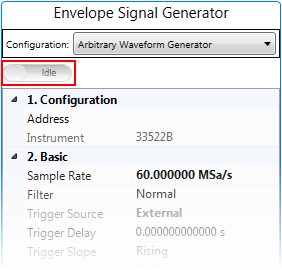
Instrument Connection button is Connected. | 1. Configuration | 2. Basic | 3. Output |
|---|---|---|
Enter the instrument address.
Default: 33522B
Instrument Connection button is Connected. Range: 1 Hz to Maximum sample rate supported by the instrument, which is 1 GHz for 33622A, 250 MHz for 33522B
Default:
PA Test: 15 MSa/s
Dual-band PA Test: 60 MSa/s
Set the sample rate of the Envelope Signal Generator. By default, this value is set to three times of the product of the Sample Rate value and Resampling Ratio value in Waveform block and the OSR for Envelope value in Envelope Tracking block.You can set it to a larger value if you like.
Choice: Normal | Step |Off
Default: Normal
Specifies the filter setting for an arbitrary waveform.
Normal filters the data points with the filter that provides the flattest frequency response. This effectively smoothes the signal, but sharp transitions will have pre-shoot and overshoot.
Step filters the data points in a way that effectively smooths the signal while minimizing the pre-shoot and overshoot. However, this setting has a narrower bandwidth than the NORMal setting.
Off steps from point to point at the sample rate. Moves between data points are accomplished as quickly as possible with no smoothing. If the <Filter> is set to OFF, the instrument uses a filter whose bandwidth limit restricts the maximum sample rate for the arbitrary waveform to 62.5 MSa/s.
Choice: External | Bus
Default:
PA Test: Bus
Dual-band PA Test: External
Coupling: Trigger Source will be coupled to External if the Trigger Master setting in the Envelope Tracking block is set to RF Signal Generator, and will be coupled to Bus if the Trigger Master setting in the Envelope Tracking block is set to Envelope Signal Generator.
Set the type of trigger source of the Envelope Signal Generator.
Range: 1 ns to 1ks
Default: 0 s
Coupling: If Envelope Tracking block is set to On and the Trigger Master in Envelope Tracking block is set to RF Signal Generator, this setting and the I/Q Delay setting in RF Signal Generator block will be determined by the Delay value in the Envelope Tracking block.
Set the trigger delay of the Envelope Signal Generator.
Choice: Rising | Falling
Default: Rising
Set the polarity of the Envelope Signal Generator's external trigger. If the Trigger Source is set to Bus, this setting is read-only.
Range: 900 mV to 3.8 V
Default: 3.3 V
Coupling: Available only when the envelope signal generator is 33622A.
Set the trigger level of the Envelope Signal Generator's external trigger. If the Trigger Source is set to Bus, this setting is read-only.
Choice: On | Off
Default: On
Double-click or use the drop-down menu to turn on or turn off the output of the Envelope Signal Generator.
Choice: 50 Ω | 100 Ω | High-Z
Default: 50 Ω
Double-click or use the drop-down menu to set the output load.
This parameter displays the current Dual Channel Operation Status. For N7614B Signal Studio for Power Amplifier Test, the value is Inverted.
Range: 0 to 7.5658 V for 33522B, 10 V for 33622B
Default: 0 V
Coupling: This value is coupled with the calculated peak to peak value of VREF.
Set the output voltage.
Range: -4.99950 V to 4.99950 V
Default: 0 V
Coupling: This value is coupled with the Vcm value in ETPS block.
Set the output voltage offset.
Range: 0.1 to 1.1 v
Default: 0.4
Coupling:
If the Envelope Source setting in the Envelope Tracking block is set to From Predistorted Signal or From Non-predistorted Signal, this value will be calculated and filled automatically when you run the measurement.
If the Envelope Source setting in the Envelope Tracking block is set to User Defined, you need to provide the value for this setting.
Set the peak voltage of the envelope signal generator. Refer to Voltage Mapping in Envelope Tracking Measurement for more details about peak voltage.
Choice: On | Off
Default: Off
Double-click or use the drop-down menu to turn on or turn off the voltage limits.
Range: -4.999 V to 5 V
Default: 5 V
Set the output voltage high limit.
Range: -5 V to 4.999V
Default: -5 V
Set the output voltage low limit.