This parameter displays the model number and serial number of the instrument if the status of  Instrument Connection button is Connected.
Instrument Connection button is Connected. | 1. Configuration | 2. Basic | 3. Output |
|---|---|---|
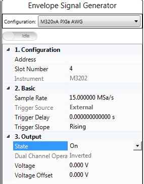
Enter the instrument address.
Displays the slot number of the chassis in which the instrument is inserted.
Default: M3202
Instrument Connection button is Connected. Range: 1 Hz to Maximum sample rate supported by the instrument
Default: 15 MSa/s
Set the sample rate of the Envelope Signal Generator. By default, this value is set to three times of the product of the Sample Rate value and Resampling Ratio value in Waveform block and the OSR for Envelope value in Envelope Tracking block.You can set it to a larger value if you like.
Choice: External | Bus
Default:
PA Test: Bus
Dual-band PA Test: External
Coupling: Trigger Source will be coupled to External if the Trigger Master setting in the Envelope Tracking block is set to RF Signal Generator, and will be coupled to Bus if the Trigger Master setting in the Envelope Tracking block is set to Envelope Signal Generator.
Set the type of trigger source of the Envelope Signal Generator.
Range: 1 ns to 1ks
Default: 0 s
Coupling: If Envelope Tracking block is set to On and the Trigger Master in Envelope Tracking block is set to RF Signal Generator, this setting and the I/Q Delay setting in RF Signal Generator block will be determined by the Delay value in the Envelope Tracking block.
Set the trigger delay of the Envelope Signal Generator.
Choice: Rising | Falling
Default: Rising
Set the polarity of the Envelope Signal Generator's external trigger. If the Trigger Source is set to Bus, this setting is read-only.
Choice: On | Off
Default: On
Double-click or use the drop-down menu to turn on or turn off the output of the Envelope Signal Generator.
This parameter displays the current Dual Channel Operation Status. For N7614B Signal Studio for Power Amplifier Test, the value is Inverted.
Range: 0 to 10 V
Default: 0 V
Coupling: This value is coupled with the calculated peak to peak value of VREF.
Set the output voltage.
Range: -4.99950 V to 4.99950 V
Default: 0 V
Coupling: This value is coupled with the Vcm value in ETPS block.
Set the output voltage offset.