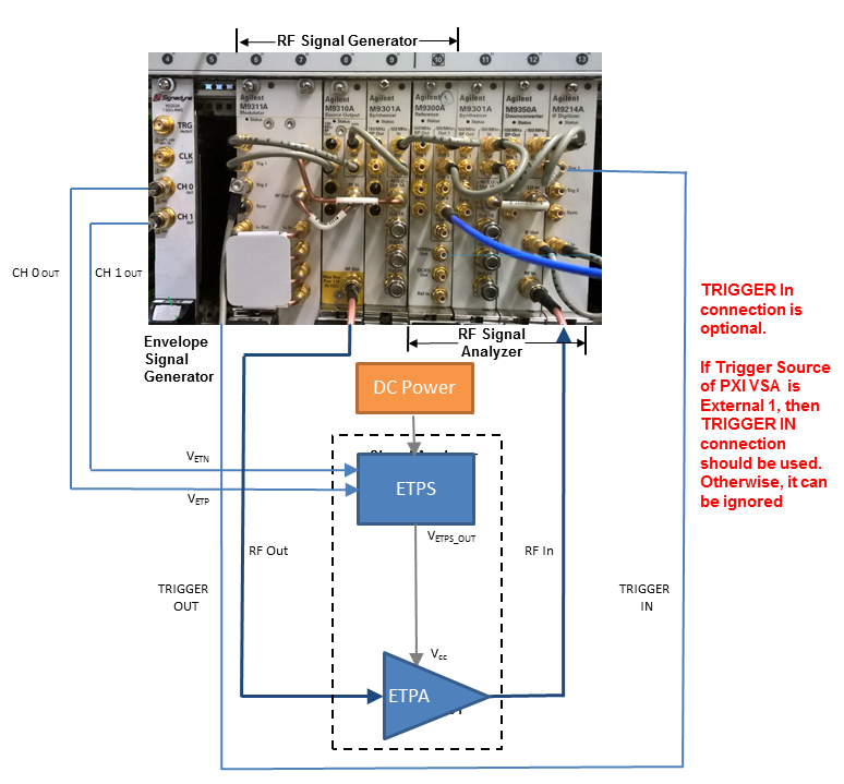
The following figure shows the instrument connection of envelope tracking measurement. The figure shows the measurement setup when M320xA PXI AWG is used as envelope signal generator.
Figure 1. Envelope tracking measurement setup when M320xA PXI AWG is used as envelope signal generator
Follow the procedure below to set up the measurement system:
Software Installation of M320xA AWG
Ensure that you have Microsoft .NET Framework 4.5 or later installed on the Windows operating system (PC or Windows-based instrument) that is to receive the Signal Studio software download.
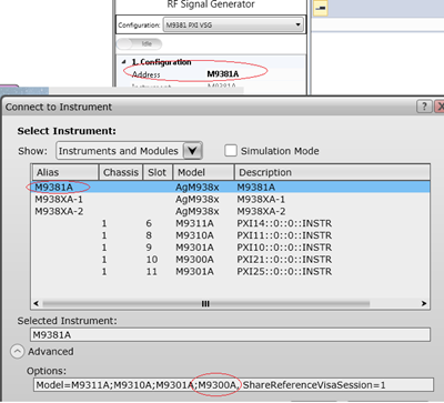
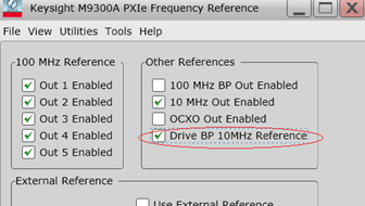
In case you select the M9381 PXIe VSG or M9391 PXIe VSA, it is necessary that one of them should at least contain M9300A Reference module:
In case none of them contains M9300A module, select the Drive BP 10MHz Reference check box from the M9300A SFP to use the 10 MHz reference signal on the backplane for the alignment of the RF signal and the envelope signal.
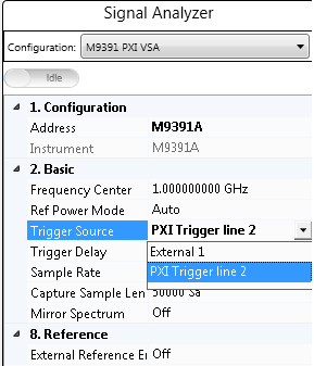
The following two options are available in the N7614B software to select the source of the trigger signal for PXIe VSA:
External means that the trigger signal originates at the Trig 1 on the M9214A front panel.
PXI Trigger line 2 means that the trigger signal originates from PXI backplane line 2. PXI Trigger Line 2 is the preferred Trigger Source and is the default value.
In case there is only one Signadyne AWG module in the PXI chassis, no need to specify the address and slot number of the AWG. N7614B software detects it automatically.
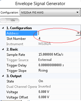
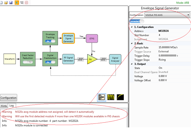
However, in case there are more than one Signadyne AWG modules in a PXI chassis, specify the exact address and slot number of the AWG in the N7614B software.
Follow the steps below to install the M320xA AWG software:
www.signadyne.com/files/Installers/FPGAflow_1.92.02_installer.exe
www.signadyne.com/files/Installers/PROCESSflow_1.92.02_installer.exe
www.signadyne.com/files/Installers/Essentials_1.92.02_installer.ex.
www.signadyne.com/files/UpdatePkgs/updatePkg_AWG_H335x_2016_09_09.sdpkg
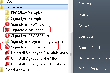
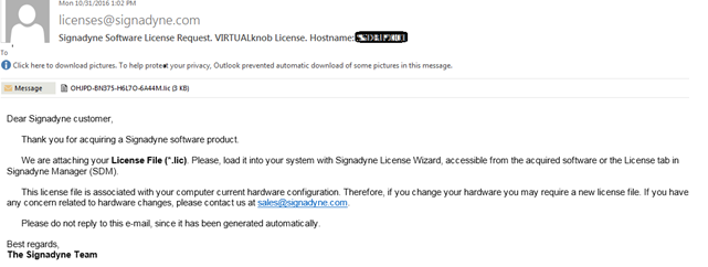
Before using Signadyne Manager and Signadyne VIRTUALknob, apply for the Signadyne software license using the instructions provided in the installation guide. Once the license request application is submitted to Signadyne, you will receive a mail shortly with your license file and instructions on how to install the license on your system.
Once the license installation is complete, launch the Signandyne Manager from the bottom-right corner on the task bar or from the Start menu.
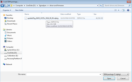
Click File > Load SDM package to load *.sdpkg file downloaded from the link below:
www.signadyne.com/files/UpdatePkgs/updatePkg_AWG_H335x_2016_09_09.sdpkg
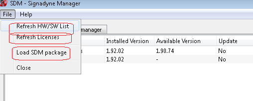
Click Refresh HW/SW List and Refresh Licenses to update the M320xA Signadyne Manager user interface and successfully install the licensed version of M320xA AWG software on your system.
The HW/SW manager tab displays the installed part number of the AWG, and the physical slot position of the AWG in PXI chassis which can be used for initialization of the AWG.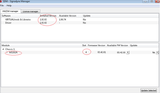
The table below shows the supported instruments for envelope tracking measurement. For details about the options required for each instrument model, see System Requirements.
| Instrument Type | Instrument Model Supported |
|---|---|
|
RF Signal Generator |
M938xA |
|
Envelope Signal Generator |
M320xA Arbitrary Waveform Generator |
|
Signal Analyzer |
M939xA |
To set up the measurement system, follow the steps below:
Connect the M320xA Envelope Signal Generator output to the ETPS. Connect the CH 0 OUT and CH 1 OUT ports of the Envelope Signal Generator to the VETP and VETN ports of the ETPS respectively and connect the VETPS_OUT port of the ETPS to the Vcc of the ETPA.
This is to synchronize the RF Signal Generator and Signal Analyzer in time domain.
Connect the Trig 2 port on the front panel of the M9311A Modulator of the RF Signal Generator to the Trig 1 port on the front panel of the M9214A Digitizer of the Signal Analyzer. Alternatively, use the trigger signal from PXI backplane line 2, PXI Trigger Line 2.Connect the RF OUTPUT port of the RF Signal Generator to the input of the PA and connect the output of the PA to the RF INPUT port of the Signal Analyzer.