 in the right side of the cell to browse the computer and select the waveform file.
This block is to load the original IQ waveform file with some basic processing, then pass it along to do further CFR/DPD processing.
|
1. Basic |
2. Processing |
3. Markers |
|---|---|---|
Choice: Preloaded | Signal Studio | User-defined
Default: Signal Studio
Specify the type of waveform. It has three different choices, Preloaded, Signal Studio and User-defined.
Preloaded – N7614B Signal Studio for Power Amplifier Test provides about eight waveforms that do not require waveform licenses to use. They are WLAN and LTE waveforms with different settings.
Signal Studio – Select this option to use the waveform generated with another Keysight Signal Studio. Refer to Creating and Exporting Waveforms for details about exporting a waveform file.
User-defined – Select this option to use a waveform in a certain format generated by the user.
Choice: CSV/Text | Big Endian 16 Bits | MATLAB
Default: CSV/Text
Coupling: Available when the Waveform Type is set to User-defined.
Specify the format of the source file when the Waveform Type is set to User-defined.
CSV/Text – .csv or .txt format: I/Q data is interleaved and delimited with commas. Example: 1.235,-3.123.
Big Endian 16 Bits – This is for unencrypted MXG/EXG waveforms. It is I/Q DAC bit value and the leftmost bit is MSB. I and Q are interleaved.
MATLAB – .mat format: This is for Matlab waveforms. If the .mat file contains several complex arrays, only the first array will be imported as the waveform.
Click the in the right side of the cell to browse the computer and select the waveform file.
Range: 1 MHz to 8 GHz
Default: 5 MHz
Coupling: This cell is read-only when the Waveform Type is set to Predefined or Signal Studio.
It indicates the sample rate used by the waveform when Waveform Type is set to Predefined or Signal Studio. Sample rate is extracted from the header file of the waveform. You need to specify the sample rate manually when the Waveform Type is set to User-defined.
Waveform Length is read-only and it indicates the sample number in the waveform.
Time Duration is read-only and it indicates the time duration of the selected waveform.
Range: 1 to 200 MHz
Default: 5 MHz
Specify the bandwidth of the waveform.
Coupling: It equals to the ratio of Sample Rate in Digital Predistortion model to Sample Rate in Waveform model.
Resampling Ratio is read-only and it indicates the oversampling ratio to be applied on the selected waveform.
Coupling: It equals to the multiplication of the Waveform Length and the Resampling Ratio.
It is read-only and indicates the sample number of the waveform after oversampling.
Set the parameters to design a Parks-McClellan low pass filter in the menu below. The Parks-McClellan design method uses the Remez exchange algorithm to design linear phase FIR filters such that a filter has minimum weighted Chebyshev error in approximating a desired ideal frequency response. For more details, refer to Chapter 7.4.3 in "The Parks-McClellan Algorithm in Discrete-Time Signal Processing, 2nd ed".
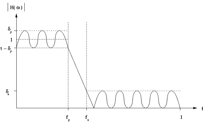
The filter can be depicted as below, in which
fp is the pass frequency,
fs is the stop frequency,
δp is the pass ripple,
δs is the stop ripple.
Choice: On | Off
Default: Off
Double-click or use the drop-down menu to enable or disable the application of the filter.
Range: 1 to 2048
Default: 300
Set the maximum filter length. The filter’s length is clipped to the Maximum Order if the minimum filter length required to satisfy its specification exceeds the Maximum Order.
Range: 1 Hz to (Stop Frequency - 0.0015*Sample Rate*Resampling Ratio in Waveform block/2)
Default: 1.25 MHz
Set the pass frequency of the filter.
Range: 2 Hz to (0.5*Sample Rate*Resampling Ratio)
Default: 1.5625 MHz
Set the stop frequency of the filter.
Range: 0.0001 to 5.0
Default: 0.01
Set the maximum ripple in the pass band.
Range: 6.0 to 200.0
Default: 50.0
Set the maximum ripple in the stop band.
Choice: None | FromWaveformFile | WaveformStart | UserDefined
Default: WaveformStart
Configure the marker points for Marker 1 using the Marker Source Selection dialog box.
The signal generator outputs the Marker 1 signal from the rear-panel EVENT 1 output. For more information, see the signal generator's User Guide.
Configure the marker points for Marker 2 using the Marker Source Selection dialog box.
The signal generator outputs the Marker 2 signal from the rear-panel EVENT 2 output. For more information, see the signal generator's User Guide.
Choice: RF ALC Control | UserDefined
Default: RF ALC Control
This parameter indicates Marker 3 is used to control ALC hold.
The signal generator outputs the Marker 3 signal from the rear-panel EVENT 3 output. For more information, see the signal generator's User Guide.
Choice: RF Blanking | UserDefined
Default: RF Blanking
This parameter indicates Marker 4 is used to control Pulse/RF Blank.
The signal generator outputs the Marker 4 signal from the rear-panel EVENT 4 output. For more information, see the signal generator's User Guide.