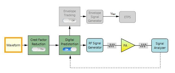
The following figure shows the block view settings in N7614B for wideband DPD measurement.
The remaining section of this topic provides an example procedure of setting N7614B for DPD measurement. Note that for different PA, the settings are different.
Step 1: Set the Waveform Block
Step 2: Set the Crest Factor Reduction Block
Step 3: Set the Digital Predistortion Block
Step 4: Set the RF Signal Generator Block
Step 6: Set the Signal Analyzer Block
Since the Waveform block has been configured in calibration step, you can skip this step if no settings under Waveform block need to be changed.
 turn Crest Factor Reduction to Through on the UI.turn on Digital Predistortion on the UI. In the right panel, do the following:
Select Extract and Apply as the DPD Mode.
Two modes are supported to perform the digital predistortion.
feedback line from the Spectrum Analyzer block to the Digital Predistortion Block on the block diagram. Apply Only is to use a user-defined PA distortion model in a form of LUT (look-up-table).
Set the Number of Iteration to 1. By setting this parameter, the extraction model will be repeated by feeding its output to the input to minimize error. Typically, setting it to 3 is enough.
Set the PA Model Type to Memory Polynomial. Refer to DPD Concept for details about different PA model types.
Set the Memory Order to 1 and set Non-linear Order to 5.
Click on the RF Signal Generator block icon on the UI. Set the PSG amplitude for PA input power. PA input power can also be set in PA block.
Click on the PA block icon on the UI. Set the Loss In, Loss Out, and PA Gain. For example set PA Gain to 20 dB.
Click on the Signal Analyzer block icon on the UI. Set the Trigger Source to External 1 and adjust Trigger Delay value as needed. If the high bandwidth channel is used for UXA H1G, the trigger source should be set to external 3.
