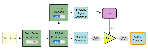
The following figure shows the block view settings in N7614B for ET+DPD measurement. In this example, both the Envelope Tracking block and the Digital Predistortion block are turned On.
The remaining section of this topic provides an example procedure of setting N7614B for ET+DPD measurement. Note that for different PA, the settings are different.
Step 1: Set the Waveform Block
Step 2: Set the Crest Factor Reduction Block
Step 3: Set the Digital Predistortion Block
Step 4: Set the Envelope Tracking Block
Step 5: Set the Envelope Signal Generator Block
Step 8: Set the RF Signal Generator Block
Step 9: Set the Signal Analyzer Block
Step 10: Set the Measurement View
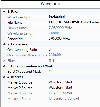
Click on the Waveform block icon on the UI. In the right panel, do the following:
Select Preloaded as the Waveform Type and select the "LTE_FDD_5M_QPSK_FullRB.wfm" file.
Set the bandwidth to 5 MHz according to the waveform bandwidth.
Set the Resampling Ratio to 3.
 turn Crest Factor Reduction to Through on the UI.turn on Digital Predistortion on the UI. In the right panel, do the following:
Set DPD Mode to Apply Only.
Set Reference (w/o DPD) to On.
Set the PA Model Type to Look-up Table. Refer to DPD Concept for details about different PA model types.
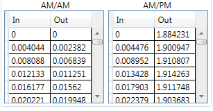
Set the LUT Type to Absolute and LUT Apply Mode to AM/AM, then AM/PM.
Enter the look-up table as below or you can also use an existing look-up table. Below is an example of the look-up table used here.
turn on Envelope Tracking on the UI. In the right panel, do the following:Set the Envelope Source to From Predistorted Signal. Then the software will calculate the envelope signal using the signal after Digital Predistortion block.
Set the Trigger Master to Envelope Signal Generator if the RF Signal Generator in use is N5172B or N5182B. Otherwise, set the Trigger Master to RF Signal Generator.
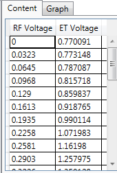
Set the Conversion Input Type to Absolute RF Output Voltage. This is to set the reference for the RF Voltage column in the shaping table.
Enter the shaping tables.This shaping table is used to map the selected Conversion Input Type, Normalized I/Q Amplitude, Absolute RF Output Voltage or Override Absolute RF, to the supply voltage of the PA (Vcc).
Here is the shaping table used as an example.
Click on the Envelope Signal Generator block icon on the UI. In the right panel, do the following:
Select the type of Envelope Signal Generator in the Configuration setting. In this example, select MXG/EXG.
connect button on the top of the window to Connected state. After the instrument is connected, the model number and serial number of the instrument will be displayed in the Instrument cell. For other values, you can use the default settings. Note that the Voltage and Voltage Offset value will be set automatically after the test flow is run.
Click on the ETPS block icon on the UI. In the right panel, do the following:
Set the ETPS Gain to 7.0 dB.
Set the Vcc Offset to 2.75 V.
Set the Vcm to 750 mV.
Click on the PA block icon on the UI. In the right panel, do the following:
Enter the PA information by setting the Loss In, Loss Out, and PA Gain.
Select PA Input as the Power Mode.
Set Power to -5 dBm. This is to set the input power of the PA. Then the Amplitude setting in RF Signal Generator block will be set to (Power + Loss In) automatically.
Click on the RF Signal Generator block icon on the UI. In the right panel, do the following:
connect button on the top of the window to Connected state. After the instrument is connected, the model number and serial number of the instrument will be displayed in the Instrument cell. Set Frequency to 2 GHz.
Click on the Signal Analyzer block icon on the UI. In the right panel, do the following:
connect button on the top of the window to Connected state. After the instrument is connected, the model number and serial number of the instrument will be displayed in the Instrument cell. Note that the Frequency value is coupled to the frequency setting in RF Signal Generator block.
Set the Trigger Source to External 1 and adjust Trigger Delay value as needed. For most cases, you can use the default value.
 button on the UI to change the current view from block view to measurement view.
 You can turn Intermediate Result to On and set the ACP parameters as required. In this example, the default settings are used.