The following figures show the instrument connection of envelope tracking measurement.
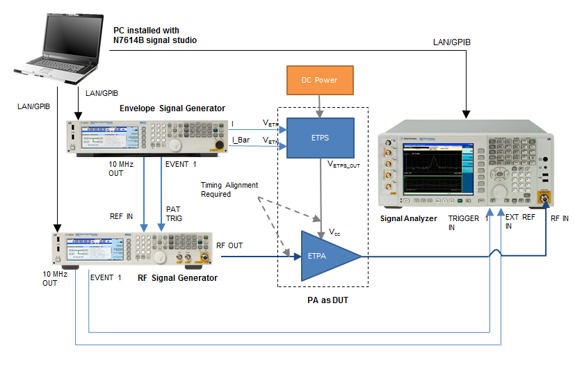
Figure 1. Envelope tracking measurement setup when N5172B EXG/N5182B MXG is used as envelope signal generator
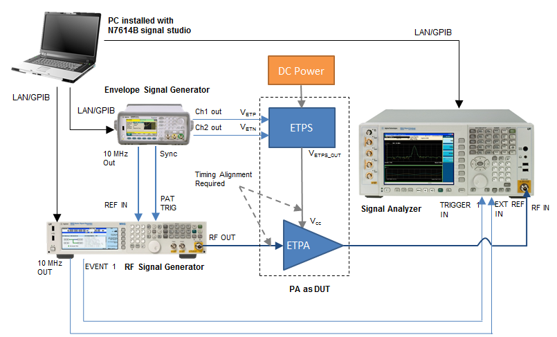
Figure 2. Envelope tracking measurement setup when 33522B/33622A is used as envelope signal generator
The table below shows the supported instruments for envelope tracking measurement. For details about the options required for each instrument model, refer to System Requirements.
| Instrument Type | Instrument Model Supported |
|---|---|
|
RF Signal Generator |
N5182B MXG N5172B EXG N5182A MXG |
|
Envelope Signal Generator |
33522B Arbitrary Waveform Generator 33622A Arbitrary Waveform Generator N5182B MXG N5172B EXG |
|
Signal Analyzer |
N9010A EXA N9020A MXA N9030A PXA |
To set up the measurement system, follow the steps below:
Connect the PC installed with N7614B Signal Studio with the RF Signal Generator, Envelope Signal Generator, and Signal Analyzer through LAN or GPIB.
Connect the 10 MHz Ref Out port of the Envelope Signal Generator to the 10 MHz Ref In port of the RF Signal Generator and connect the EVENT 1 port of the Envelope Signal Generator to the PAT TRIG port of the RF Signal Generator for time alignment of the Envelope Signal Generator output and RF Signal Generator output.
If N5172B/N5182B is used as envelope signal generator, connect the I OUT and  OUT of the Envelope Signal Generator to the VETP and VETN port of the ETPS and connect the VETPS_OUT port of the ETPS to the Vcc of the ETPA.
If 33522B or 33622A is used as envelope signal generator, connect the Channel 1 and Channel 2 output of the Envelope Signal Generator to the VETP and VETN port of the ETPS and connect the VETPS_OUT port of the ETPS to the Vcc of the ETPA.
Connect the EVENT 1 port on the rear panel of the RF Signal Generator to the Trigger IN 1 port on the rear panel of the Signal Analyzer using a BNC cable. This is to synchronize the RF Signal Generator and Signal Analyzer in time domain.
Connect the 10 MHz OUT port on the rear panel of the RF Signal Generator to the EXT REF IN port on the rear panel of the Signal Analyzer using a BNC cable.
Connect the RF OUTPUT port of the RF Signal Generator to the input of the PA and connect the output of the PA to the RF INPUT port of the Signal Analyzer.