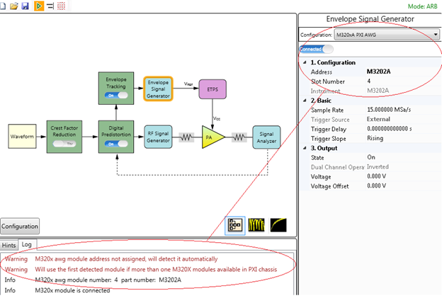
The following figures shows the measurement setup when VXT/AWG M320xA is used as envelope signal generator for envelope tracking and DPD measurement. Figure 1 shows the measurement setup when M320xA AWG is used as envelope signal generator. Figure 2 shows the hardware connection that can be used to support DPD, but make sure no envelope signal goes into the ETPS. Figure 3 shows another hardware connection that can be used to support DPD.
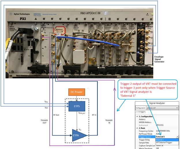
Figure 1. Envelope Tracking Measurement Setup when VXT/AWG M320xA is used as Envelope Signal Generator
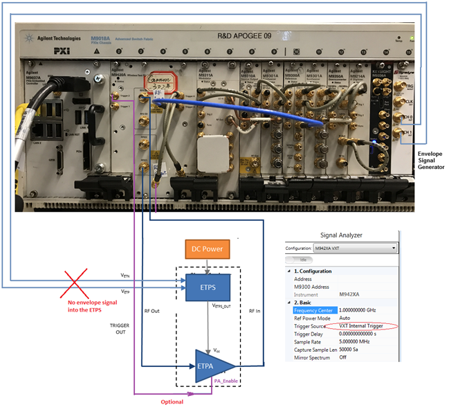
Figure 2. DPD Measurement Setup
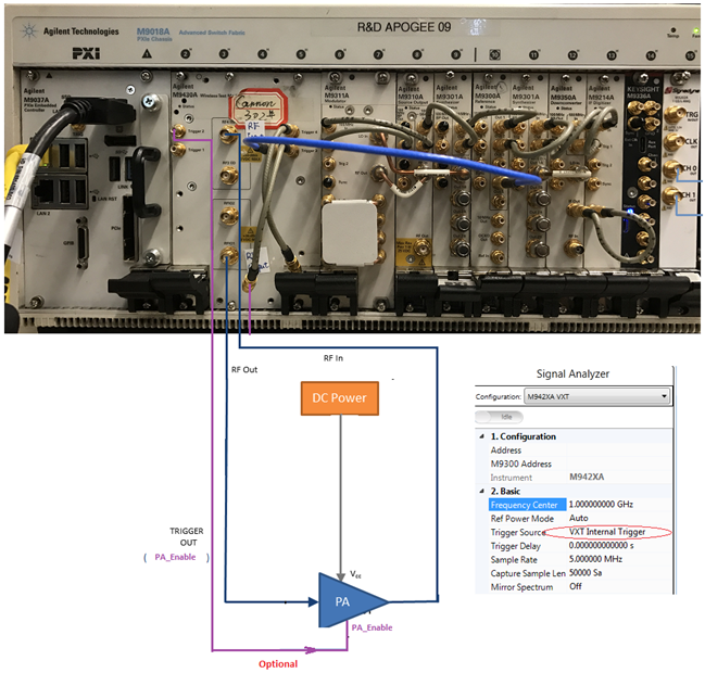
Figure 2. DPD Measurement Setup
Follow the procedure below to set up the measurement system:
Software Installation of M320xA AWG
Ensure that you have Microsoft .NET Framework 4.5 or later installed on the Windows operating system (PC or Windows-based instrument) that is to receive the Signal Studio software download.
When assigning the address of VXT module, the VXT source address is needed to control the VXT. The Address drop-down in the RF Signal Generator block displays the addresses of all the VXT sources. In case the drop-down is empty, it means that no VXT module can be detected, and the instrument connections need to be verified.
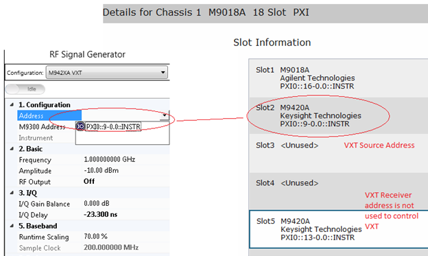
The M9300A address can be assigned directly or selected or left empty. In case the address is left empty, the N7614B software will not handle the initialization of M9300A module.
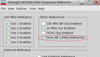
In case you select the M9300A module, select the Drive BP 10MHz Reference check box from the M9300A SFP to use the 10 MHz reference signal on the backplane for the alignment of the RF signal and the envelope signal.
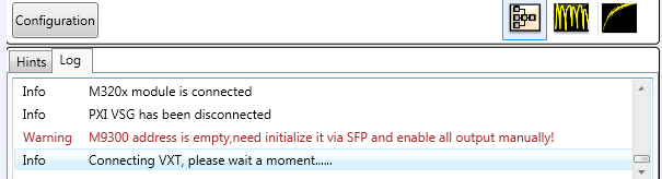
In case the M9300 address field is left empty, no 10 MHz reference signal originates from the backplane. The Signadyne AWG loses the reference signal and there is no way to align RF signal and envelope signal. The VXT modules cannot work because it need 100 MHz reference signal from M9300A module.
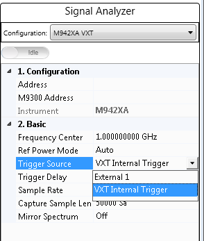
The following two options are available in the N7614B software to select the source of the trigger signal for VXT receiver:
External 1 means that the trigger signal originates at the Trigger 3 port on the VXT front panel.
VXT Internal Trigger means that the trigger signal originates from the VXT source via the VXT internal line. VXT Internal Trigger is the preferred Trigger Source and is the default value.
In case there is only one Signadyne AWG module in the PXI chassis, no need to specify the address and slot number of the AWG. N7614B software detects it automatically.
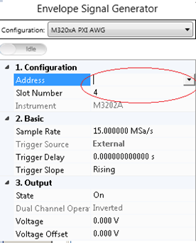
However, in case there are more than one Signadyne AWG modules in a PXI chassis, specify the exact address and slot number of the AWG in the N7614B software.
Follow the steps below to install the M320xA AWG software:
www.signadyne.com/files/Installers/FPGAflow_1.92.02_installer.exe
www.signadyne.com/files/Installers/PROCESSflow_1.92.02_installer.exe
www.signadyne.com/files/Installers/Essentials_1.92.02_installer.ex.
www.signadyne.com/files/UpdatePkgs/updatePkg_AWG_H335x_2016_09_09.sdpkg
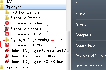
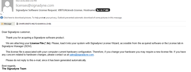
Before using Signadyne Manager and Signadyne VIRTUALknob, apply for the Signadyne software license using the instructions provided in the installation guide. Once the license request application is submitted to Signadyne, you will receive a mail shortly with your license file and instructions on how to install the license on your system.
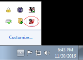
Once the license installation is complete, launch the Signandyne Manager from the bottom-right corner on the task bar or from the Start menu.
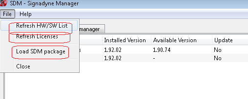
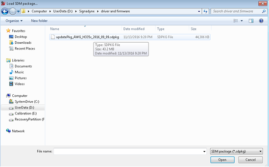
Click File > Load SDM package to load *.sdpkg file downloaded from the link below:
www.signadyne.com/files/UpdatePkgs/updatePkg_AWG_H335x_2016_09_09.sdpkg
Click Refresh HW/SW List and Refresh Licenses to update the M320xA Signadyne Manager user interface and successfully install the licensed version of M320xA AWG software on your system.
The HW/SW manager tab displays the installed part number of the AWG, and the physical slot position of the AWG in PXI chassis which can be used for initialization of the AWG.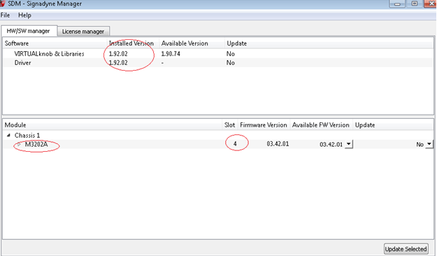
The following mandatory license files must be available in the PXI controller:
N7614B-9FP
N7614B-EFP
N7614B-FFP
The table below shows the supported instruments for envelope tracking measurement. For details about the options required for each instrument model, see System Requirements.
| Instrument Type | Instrument Model Supported |
|---|---|
|
RF Signal Generator |
M942XA VXT |
|
Envelope Signal Generator |
M320xA PXI Arbitrary Waveform Generator |
|
Signal Analyzer |
M942XA VXT |
To set up the ET measurement system, follow the steps below:
To simplify the scenario, only CH 0 and CH 1 of the M320xA module (with two channels or four channels)are used for envelope tracking. Connect the CH 0 and CH 1 of the M330xA module to the VETP and the VETNports of the ETPS respectively.
Connect the Trigger 2 output to the Trigger 3 port of the VXT only if the Trigger Source of VXT Signal analyzer is set to External 1 in the N7614B software. In case you select the VXT Internal trigger option, connect the Trigger 2 output to the oscilloscope for monitoring purpose.
The RF Input and the RF Output ports are used for VXT Source Output and VXT Receiver Input respectively. The RFIO port is not used.
To set up the DPD measurement system, follow the steps below:
If PA does not need PA_Enable signal, connect the Trigger 2 output to the Trigger 3 port of the VXT if the Trigger Source of VXT Signal analyzer is set to External 1 in the N7614B software. In case you select the VXT Internal trigger option, connect the Trigger 2 output to the oscilloscope for monitoring purpose.
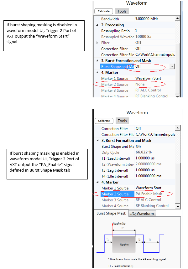
If PA needs PA_Enable signal to work in burst mode, use the VXT Internal Trigger option as the Trigger Source of VXT Receiver. In this case, the Trigger 2 port outputs the PA_Enable signal defined in Burst Shape and Mask drop-down (see Waveform Block GUI)
The RF Input and the RF Output ports are used for VXT Source Output and VXT Receiver Input respectively. The RFIO port is not used.