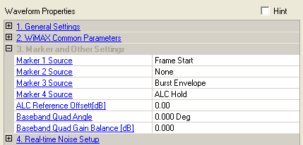

Double-click or use the drop-down menu to select the type of signal output for each marker. The markers are set to go high for selected events.
The software uses Marker 3 to control the RF blanking and Marker 4 for ALC settings. These settings should be changed unless you know how the changes will affect the waveform playback.
– selects no signal output. This is the default for Marker 2.
– selects high signal output at the start point of the waveform.
– selects high signal output at each frame start. This is the default for Marker 1.
– selects high signal output when the burst (except for gap) is active. This is the default for Marker 3.
– assigns a specific marker to activate the automatic leveling control (ALC) function. When enabled, the ALC constantly monitors and controls the RF output power of the ESG. This is the default setting for Marker 4.
- provide frame start marker after cyclic prefix of preamble.
Range: –15 to 0 dB
Specify the power offset for the ALC hold marker. This value is specified as the offset from the highest symbol in the frame. This parameter is coupled with Power Envelope Plot.
Range: –90 to 90 degrees
Add quadrature skew impairment to the generated waveform. This affects the waveform data so it applies to both RF and baseband I/Q outputs.
Range: –10 to 10 dB
Add quadrature gain impairment to the generated waveform. This affects the waveform data so it applies to both the RF and baseband I/Q outputs.
The Baseband Quadrature Angle (angle) and the Baseband Quadrature Gain (gain) values are used to modify the output I and Q data according to the following equations:
Real (output) = Real (input) + Gs * Imag (input)
Imag (output) = Gc* Imag (input)
where:
Gs = Gain * sin (angle) and
Gc = Gain * cos (angle)