When an M9381A/M9383A is connected, you will see the display as below:
When an M9383B/M9384B/M9484C is connected, you will see the display as below:
(MXG/EXG only)
Choice: On | Off
Default: Off
The internal channel correction feature corrects the 100 MHz baseband bandwidth flatness and phase for arbitrary center frequencies. This feature is off by default, as the switching speed performance of the instrument is impacted when this feature is on.
This calibration should be run when the ambient temperature has varied by at least ±5 degrees Celsius from the ambient temperature at which the previous calibration was run. For more information about this feature, refer to the Keysight X-Series Signal Generators user's guide.
(M9383B/M9384B/M9484C only)
Choice: On | Off
Default: On
Double-click or use the drop-down menu to turn the internal channel correction Off or On.
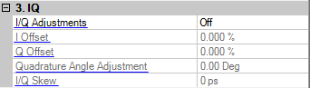
Choice: On | Off
Default: Off
Double-click or use the drop-down menu to turn the I/Q adjustments on or off.
On − the values entered for I and Q parameters are applied to the I and Q signals.
Off − I/Q adjustment values are not applied to the I and Q signals.
Range:
N5182A: –20% to 20%
All other models: –50% to 50%
Default:
0.0%
Set to to enable this parameter.
Enter a DC offset value to apply to the I signal before the I/Q modulator. Use this offset to remove imperfections in the in-phase signal or to introduce calibrated impairments.
For more information, refer to the User Guide or Key Reference for the signal generator you are using
Range:
N5182A: –20% to 20%
All other models: –50% to 50%
Default:
0.0%
Set to to enable this parameter.
Enter a DC offset value to apply to the Q signal before the I/Q modulator. Use this offset to remove imperfections in the quadrature-phase signal or to introduce calibrated impairments.
For more information, refer to the User Guide or Key Reference for the signal generator you are using.
(M9383B/M9384B/M9484C only)
Range: -1 dB to 1 dB
Default: 0 dB
Set to to enable this parameter.
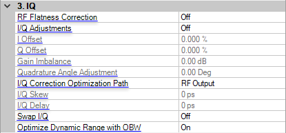
Enter a gain ratio, by which I gain exceeds Q gain.
For example, if you enter a value of 1 dB, the I signal will have 1 dB more amplitude than the Q signal. Use the gain balance to remove imperfections in I and Q or introduce calibrated impairments.
Range:
N5182A: –1 dB to 1 dB in 0.001 dB steps
All other models: –4 dB to 4 dB in 0.01 dB steps
Default:
0.00 dB
Set to to enable this parameter.
Enter a gain ratio, by which I gain exceeds Q gain.
For example, if you enter a value of 1 dB, the I signal will have 1 dB more amplitude than the Q signal. Use the gain balance to remove imperfections in I and Q or introduce calibrated impairments.
Range: −10 to 10 degrees
Default: 0.00 degrees
Set to to enable this parameter.
Enter a value to adjust the Q phase angle. When the quadrature skew is zero, the phase angle between the I and Q vectors is 90 degrees. Positive skew increases the angle from 90 degrees while negative skew decreases the angle from 90 degrees.
Choice: RF | Baseband (BB)
Default: RF
Set to to enable this parameter.
Double-click or use the drop-down menu to select whether the path is RF or Baseband (BB).
This parameter is not available with all instrument model numbers and may be grayed out.
Choice:
N5172B/N5182B: RF Output | External I/Q Output | Dig Bus Output
Other Models: RF Output | External I/Q Output
Default: RF Output
Set to to enable this parameter.
Double-click or use the drop-down menu to select the I/Q Correction optimization path.
optimizes the RF OUT path by applying calibration factors to only this path, leaving the I/Q OUT and Digital Bus paths uncalibrated.
Note: With as the I/Q Source selection, the signal generator automatically optimizes all paths, so no optimization path selection is needed.
optimizes the I/Q OUT path by applying calibration factors to only this path, leaving the RF OUT and Digital Bus paths uncalibrated.
Note: With as the I/Q Source selection, the signal generator automatically optimizes all paths, so no optimization path selection is needed.
optimizes the Digital Bus path by applying calibration factors to only this path, leaving the RF OUT and I/Q OUT paths uncalibrated.
With External as the I/Q Source selection, the signal generator automatically optimizes all paths, so no optimization path selection is needed.
Range:
N5182A: −800 ns to 800 ns, in 1 ps steps
All other models: −2.0 to 2.0 seconds, in 1 ps steps
Default:
0.0 seconds
Set to to enable this parameter.
This cell inputs skew changes to the I and Q paths, in picoseconds. A positive value delays the I signal relative to the Q signal, and a negative value delays the Q signal relative to the I signal.
Range: −1.0 to 1.0 seconds in 1 ps steps
Default: 0.0 seconds
Set to to enable this feature.
This cell sets the I/Q delay from triggers and markers, in picoseconds. Enter a value to change the absolute phase of both I and Q with respect to triggers and markers. A positive value delays I and Q. This value affects both the external I/Q out signals and the baseband signal modulated on the RF output. This adjustment cannot be used with constant envelope modulation and does not affect external I/Q inputs.
The limits are determined by the rate of the current format
(M9383B/M9384B/M9484C only)
Choice: On | Off
Default: Off
Double-click or use the drop-down menu to enable or disable the inverse phase rotation of the IQ signal by swapping the I and Q inputs.
(M9383B/M9384B/M9484C only)
Choice: On | Off
Default: On
Filters the system RF flatness correction coefficients over the instantaneous bandwidth indicated in the waveform header (or in the “Occupied Bandwidth” settings area under the Signal block when Waveform File is the Vector Modulation Signal Mode). This has the potential to improve EVM performance by not having to correct for flatness errors outside the requested bandwidth.