In 802.11 OFDM systems, information is transmitted in frames. During the burst, the entire frame is transmitted, then the carrier is idle for a certain interval. This idle interval can be set in the software. All data in the frame is OFDM encoded, and the total frame length is variable because the payload can be varied between 0-4095 bytes. The following figure illustrates the frame structure of the signal created by the Signal Studio for WLAN software, 802.11a/b/g/j/p option. The signal is created according to the IEEE-802.11a standard.
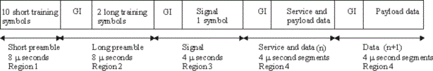
The 802.11 OFDM frame has four distinct regions. The first region of the preamble consists of a short preamble. The short preamble contains 10 short symbols assigned to subcarriers -24, -20, -16, -12, -8, -4, 4, 8, 12, 16, 20, 24. The second region contains the long preamble, consisting of 2 long symbols that are assigned to all 52 subcarriers. The preambles are BPSK modulated at 6 Mbps. They contain no channel coding, and are not scrambled. The third region of the frame is the Signal field, which consists of one OFDM symbol assigned to all 52 subcarriers. This symbol is BPSK modulated at 6 Mbps and is encoded at a ½ rate. The Signal field is not scrambled. The last region of the frame consists of the Service field and the data payload. This region is scrambled. The data rate, encoding rate, and modulation varies. Refer to the following figure. Notice that guard intervals (GI) are added to the long preamble, Signal field, and the Service and payload data.
Figure 1. N7617C Signal Studio for WLAN 2026 Update 1.0 Frame
The following figure shows a detailed diagram of a WLAN OFDM frame.
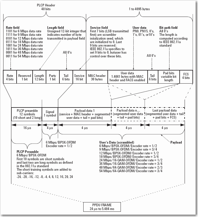
Figure 2. N7617C Signal Studio for WLAN 2026 Update 1.0 OFDM Framed Signal
These four regions comprise a PPDU frame. A MAC header and FCS can be added to the user's data. The following table provides a summary of the payload characteristics in 802.11 OFDM mode.
Table 1. OFDM payload characteristics supported with the N7617C Signal Studio for WLAN 2026 Update 1.0 software
|
Modulation |
Encoding rate |
Coded bits per sub-carrier |
Coded bits per symbol |
|
|---|---|---|---|---|
|
For 802.11a/b/g/j/p 20 MHz Channel Spacing |
||||
|
6 |
BPSK |
1/2 |
1 |
48 |
|
9 |
BPSK |
3/4 |
1 |
48 |
|
12 |
QPSK |
1/2 |
2 |
96 |
|
18 |
QPSK |
3/4 |
2 |
96 |
|
24 |
QAM-16 |
1/2 |
4 |
192 |
|
36 |
QAM-16 |
3/4 |
4 |
192 |
|
48 |
QAM-64 |
2/3 |
6 |
288 |
|
54 |
QAM-64 |
3/4 |
6 |
288 |
|
For 802.11j/p 10 MHz Channel Spacing |
||||
|
3 |
BPSK |
1/2 |
1 |
48 |
|
4.5 |
BPSK |
3/4 |
1 |
48 |
|
6 |
QPSK |
1/2 |
2 |
96 |
|
9 |
QPSK |
3/4 |
2 |
96 |
|
12 |
QAM-16 |
1/2 |
4 |
192 |
|
18 |
QAM-16 |
3/4 |
4 |
192 |
|
24 |
QAM-64 |
2/3 |
6 |
288 |
|
27 |
QAM-64 |
3/4 |
6 |
288 |
The following figure is an illustration of the payload structure. The payload data (user's data) is called PLCP service data unit (PSDU) in the standard. The description and details of the medium access control (MAC) header and frame check sequence (FCS) can be found in the IEEE 802.11 standard. The MAC header and FCS state can be turned ON or OFF. All the fields in the MAC header can be modified.
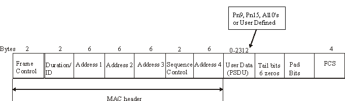
Figure 3. OFDM payload structure