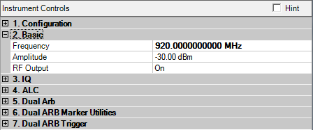
When M9381A is connected, you will see the display as below:
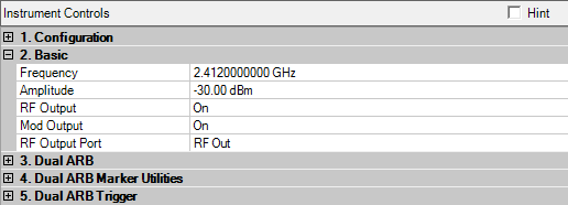
When M9420A/M9421A is connected, you will see the display as below:
Range: for specified range values, see the signal generator's data sheet
Enter a value to set the signal generator’s output frequency. Use abbreviations for faster entry (example: 1g = 1.000000000000 GHz).
Range: for specified range values, see the signal generator's data sheet
Enter a value to remotely set the signal generator’s output amplitude.
In a typical MIMO system, the average power of the signal transmitted by each antenna is different than the average power transmitted by the other antennas. For example, a difference in average power can be caused by preambles or other reference signals that are present on some antennas and not on others.
When connected to a PXB Baseband Generator and Channel Emulator, Signal Studio provides a separate Relative Amplitude cell for each antenna to display this difference in average power. For example, if you set up a two-antenna configuration in the System Configuration Wizard, the software displays two Relative Amplitude cells.
When you generate the waveform, the software sets the power in the Relative Amplitude cells based on the current waveform settings. The value in each Relative Amplitude cell represents the power in the corresponding baseband generator (BBG) on the PXB relative to the power in the other BBGs.
For more information, refer to the PXB's online documentation.

Range: 1 to 16
Default: 1
When you establish a connection between the Signal Studio software and the PXB, Signal Studio recognizes the number of baseband generators (BBGs) in the currently loaded PXB configuration. Signal Studio creates a waveform file (Ant0, Ant1, Ant2, and so on) for each antenna configured in the System Configuration Wizard. The default behavior is for Signal Studio to download waveform file Ant0 to BBG1 in the PXB, waveform file Ant1 to BBG2, and so on. In the Baseband Channel Assignment cell, the default BBG assignments are displayed as a comma-separated list (1,2).
The Baseband Channel Assignment parameter enables you control the assignment of each waveform file to a specific BBG resource, rather than accepting the default. You can assign Ant0 to BBG2 and Ant1 to BBG1 by making the corresponding change to the comma separated list (2,1).
Choice: On | Off
Default: On
Double-click or use the drop-down menu to control the signal generator’s RF output state.
Choice: On | Off
Default: On
Double-click or use the drop-down menu to turn the signal generator’s RF modulation On or Off. This function turns on or off all enabled modulation formats including I/Q modulation, pulse modulation, AM, FM and so on.
Choice: On | Off
Default: On
Double-click or use the drop-down menu to select the signal generator’s RF output port.
Coupling : The M9420A has 3 output ports: RF Out, RFIO HD and RFIO FD. The M9421A has two output ports: RF Out and RFIO HD.