AC signal is defined in ISDB-T standard and is used to convey additional information on modulating signal-transmission control or earthquake alarm information. The earthquake alarm information is transmitted using AC of the center Segment (segment No.0).
AC builder is a built-in tool, with which you can generate the AC bits easily. Below is the procedure of using the AC builder to generate the AC bits for ISDB-T/Tsb or ISDB-Tmm signals. It contains four steps:
Step 1: Locate and open the AC builder
Step 2: Configure the report(s) to be included in the AC signal
Step 3: Set the initial synchronization signal, mode, and segment number of current signal
Step 4: Generate the AC signal
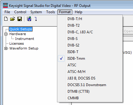
Select the ISDB-T
or ISDB-Tmm format under the Format
menu in the menu bar.
Using AC Builder in ISDB-T format requires N7623C-Mxx (ISDB-Tmm Advanced, ISDB-T enhancement) license. If this license is not installed in the connected instrument, the AC Builder can not be used to generate AC bits for ISDB-T waveform.
In the ISDB-T settings or
ISDB-Tmm segment settings table, first, in AC Setup cell select AC Builder
Tool as AC Setup type, and then click on the in the right side of the AC cell to open
the AC builder.
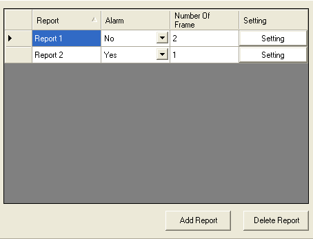
Take setting the Report1 in the figure below as an example. You can add a report or delete existing report(s) by clicking the
or button.In the Alarm column, click the drop down menu to select whether this is alarm in this report.
In the Number of Frame column, enter the number of frames this report will be included in.
Click the
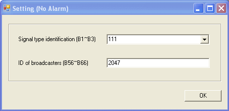
button in the setting column to configure the settings of the report.If the Alarm is set to No, the setting dialog is as below. Then select the Signal type identification (B1~B3) and enter the ID of the broadcasters.
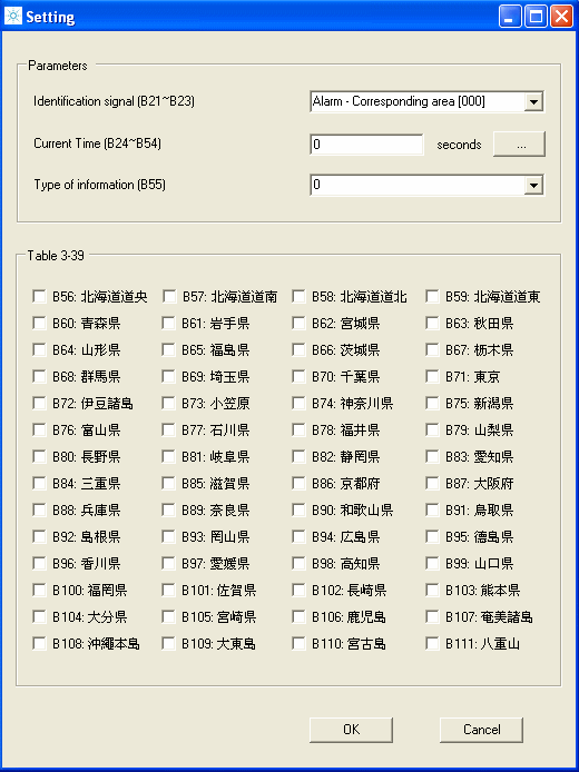
If the Alarm is set to Yes, the setting dialog is as below. Set the parameters in sequence.
Select the Identification signal (B21~B23). The table below lists the description of the identification signal.
B21~ B23 | Description |
---|---|
000 | Earthquake alarm detailed information (Corresponding area) * |
001 | Earthquake alarm detailed information (Non-corresponding area) ** |
010 | Test earthquake alarm detailed information (Corresponding area) * |
011 | Test earthquake alarm detailed information (Non-corresponding area) *note 2 |
Notes:
* In this case, the certain area is included in the broadcasting area.
** In this case the certain area is not included in the broadcasting area.
Click
to set the current time and reference time in the
time setting window.
Select the type of information (B55) and configure the corresponding information.
If
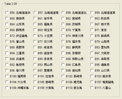
B55 is set to “0”, the areas in which the alarm is given are represented
by B56-B111 and Table
3-39
is displayed in the lower part of the setting dialog. Then select the
area the alarm is given by clicking on the corresponding check box.
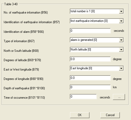
If B55 is set to “1”, the information about earthquake
center is transmitted by B56-B11 and Table 3-40
is displayed in the lower part of the setting dialog. Then set the parameters
according to the alarm information.
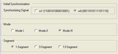
Under Initial Synchronization, select the Synchronizing Signal under use.
Under Mode, select the Mode under use.
Under Segment, select the segment number included in the signal.
Click the
button in the right bottom of the AC Builder to generate the AC signal.