This topic describes the Super Frame Structure for the N7623C Signal Studio for Digital Video software. Sections in this topic include:
Start of Super-Frame (SOSF) Field
Super-Frame Format Indicator (SFFI) Field
Super-Frame-aligned Pilots (SF-Pilots)
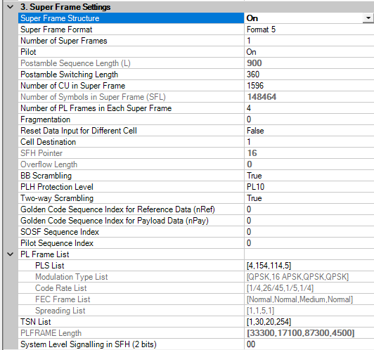
Super Frame Structure is defined in Annex E in ETSI EN 302 307-2. In N7623, we support the signal generation for super frame 5 and 6.
|
Name |
Ranges |
Note |
|
Super Frame Structure |
On | Off |
Default is Off. |
|
Number of Super Frames |
1~100 |
Default is 1. |
|
Number of CU in Super Frame |
6~100,000 |
Default is 1596. It can be an array when the number of super frames is more than one. |
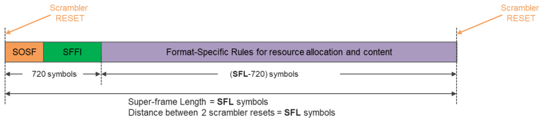
As the following figure shows, each super-frame starts with a SOSF (Start-Of-Super-Frame) preamble and a SFFI (Super-Frame Format Indicator), with a total length of 720 symbols. SFFI indicates the actual super-frame format type. The remaining part (after SFFI) can be allocated by the payload, i.e. PLHEADERs, XFECFRAMEs, and pilot fields.
The SOSF sequence comprises 270 symbols. The SOSF defining a binary sequence is composed of a 256-bit long Walsh-Hadamard (WH) sequence plus padding of 14 bits. Total 256 (= 2^8) orthogonal WH sequences generated by applying  starting from
  until
until  is deduced, where the i-th row of
  corresponds to the i-th WH sequence with i = 0, …, 255. Then a matrix of size 256 × 14 is appended, generated from H16 by deleting the first and the last column, i.e.
 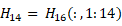 , and repeat
  vertically to get:
  . Putting both matrices together yields the HSOSF hosting the whole set of possible SOSF sequences hi row by row.
  . The selection of i is a static choice for the transmitted signal. Different signals may feature different i-values, which are considered to be a priori knowledge for the terminal. Chosen sequence hi is multiplied by (1 + j) / sqrt(2), before reference data scrambling.
|
Name |
Ranges |
Note |
|
SOSF Sequence Index |
0~255 |
Default is 0. It can be an array when the number of super frames is more than one. |
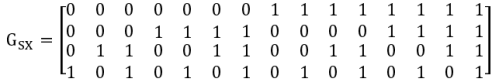
4 information bits  corresponding to format type (value from 0 to15), mapping to 15 bits codeword
  through the coder with generator matrix as below (code rate 4/15):
Each bit of  is transmitted 30 times, which yields the 1×450 vector
  . Spread codeword
  normalized by
  , before payload data scrambling.
|
Name |
Ranges |
Note |
|
Format |
Format 5 | Format 6 |
Default is Format 5 |
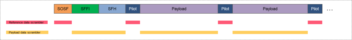
Two parallel scramblers are applied as shown in the following figure. Reference data scrambler with sequence CnRef(iRef) applied at least to the SOSF and potentially to SF-aligned pilots. Payload data scrambler with sequence CnPay(iPay)applied at least to the SFFI.
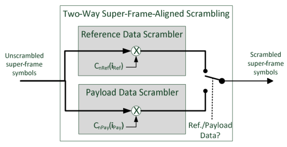
In Two-way Scrambling, both scramblers are reset jointly at each super-frame start and run synchronously, i.e. iRef = iPay always holds for the scrambling sequence indices.
At the SF start the switch is in the upper position. Then, it is switched to the lower position at the end of SOSF until the first pilot field is encountered. At the beginning of the pilot field the switch is moved back to upper position until the end of pilot field; the next pilot field is treated identically until the end of the SF is reached.
The scrambling code sequences shall be constructed by combining two real m-sequences (generated by means of two generator polynomials of degree 20) into a complex sequence. The resulting sequences are the basis for a set of Gold sequences. The selection of the scrambling code numbers nRef and nPay depends on the interference scenario faced by the system.
|
Name |
Ranges |
Note |
|
Two Way Scrambling |
On | Off |
Default is On. Off is just for debugging |
|
Golden Code Sequence Index for Reference Data (nRef) |
0~2^20-1 |
Default is 0. It can be an array when when number of super frames is more than one. This is visible only when "Two Way Scrambling" is on. |
|
Golden Code Sequence Index for Payload Data (nPay) |
0~2^20-1 |
Default is 0. It can be an array when when number of super frames is more than one. This is visible only when "Two Way Scrambling" is on. |
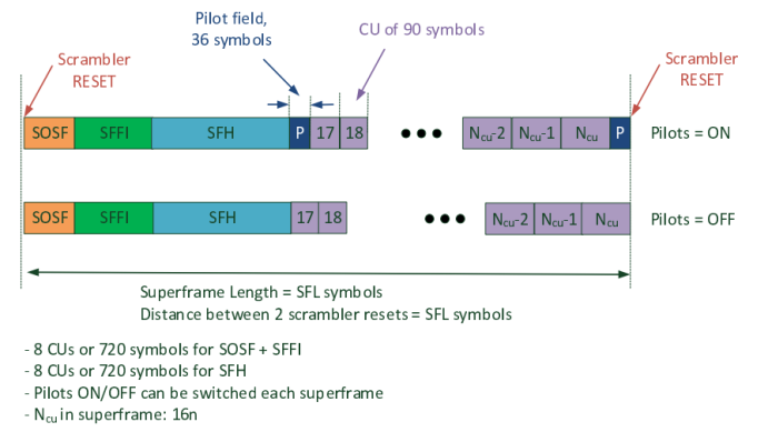
The super-frame pilots of type A follow the following configuration:
CU (Capability Unit) size = 90 symbols
Pilot field distance: dSF = 16 CUs = 1,440 symbols
Pilot field size: PSF = 36 symbols
The pilot fields of length 36 symbols are regularly inserted after each 16 CUs, counting from the start of super-frame including the CUs for SOSF/SFFI (8 CUs = 720 symbols in total).
The regularity of the pilot grid also holds from super-frame to super-frame in case pilots remain switched ON by format selection or format-related signaling.
SF pilot fields are determined by a Walsh-Hadamard (WH) sequence of size 32 plus padding of 4 bits. A set of 25 = 32 orthogonal WH sequences generated by applying  starting from
  until
until  is deduced, where the i-th row of
  corresponds to the i-th WH sequence with i = 0, …, 31. Then a matrix of size 32 × 4 is appended, generated from
  by repeating
  vertically to get:
  . Putting both matrices together yields the possible pilot sequences hi row by row.
  . The selection of i is a static choice for the transmitted signal. The chosen sequence hi is multiplied by (1 + j) / sqrt(2).
|
Name |
Ranges |
Note |
|
Pilot |
On | Off |
Can be an array |
|
Pilot Sequence Index |
0~31 |
Default is 0. It can be an array when the number of super frames is more than one. |
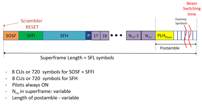
The resulting super-frame structure using format 5 is visualized in the following figure. The length of the super frame will be determined according to the following rules:
A super frame which is not the last one in a dwell time, will be of a length taken from the set: SFL=n*1476. The super frame shall then be terminated by a pilot field and followed by the SOSF of the next super frame.
The last super frame in a dwell can be of any required length (down to CU or Pilot field granularity) and shall be terminated by a post-amble.
The header of the last PLFRAME in a super frame is indicated by using a PLS bit u7.
Super-Frame Header (SFH) is constructed by the following steps:
Step 1: 16 information bits:
11-bit pointer to first complete PLH occurring in the current super-frame (counting in CUs).
2-bit PLI (PLH protection level index) within the current super-frame:
'00': PLH spreading = 1, BPSK modulation (standard protection). => Highest payload spreading factor within this super-frame = 1.
'01': PLH spreading = 2, BPSK modulation (robust protection). => Highest payload spreading factor within this super-frame = 2.
'10': PLH spreading = 5, BPSK modulation (most robust protection). => Highest payload spreading factor within this super-frame = 5.
'11': PLH punctured, QPSK modulation (high efficiency protection). => Only allowed for 8PSK payload MODCODS and above within this super-frame.
bit pilots ON/OFF: 0 = SF-pilots OFF, 1 = SF-pilots ON.
2-bit system level signaling, free for allocation by the system implementor, Default value is all zeros.
Step 2: 16 information bits going through tail-biting convolutional coder to get 80 output bits.
Step 3: Bit-wise repetition with a repetition factor of 9 to get 720 output bits (overall code rate = 1/45). SFH size is 720 BPSK symbols, which corresponds to 8 CUs. (1 CU = 90 symbols)
Step 4: Normalization: multiplied by (-2 * CSFH + 1) * (1 + j) / sqrt(2)
Pointer value (11-bit) starting from 0 (pointing to SOSF). Values from 0 to 15 are not valid (CU’s hosting SOSF, SFFI, SFH). Valid pointer value starts from 16.
|
Name |
Ranges |
Note |
|
PLH Protect Level |
PL00 | PL01 | PL10 | PL11 |
Can be an array and the length is the sum of "number of frames in Super Frame". |
|
System Level Signaling in SFH |
00 | 01 | 10 | 11 |
It can be an array when the number of super frames is more than one. |
|
SFH Pointer |
An array with length = number of super frames |
This is read-only and calculated by SFL and frame settings. |
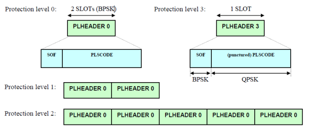
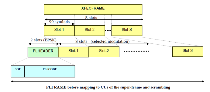
The PLH is constructed from a concatenation of a SOF and a PLSCODE (20 symbols and 160 symbols for standard protection). SOF Sequence contains 20 known symbols with bit sequence CSOF = [1 0 0 1 1 1 0 1 0 1 0 1 0 1 1 0 0 1 0 0] (0x9D564) as start of PLH. BPSK modulation is applied to the SOF sequence by  .
.
PLSCODE is constructed by the following steps:
Step 1: 16 information bits:
8 bits MOD/COD/SPREAD/SIZE
(u0, u1, u2, u3, u4, u5, u6) = 7 bits PLS Code signaling for MOD/COD/SPREAD/SIZE signaling
(u7) = TYPE "pilot" bit used for last PLFRAME in the super-frame, allowing receiver to prepare for super frame ending or illumination dwell time ending:
u7 = 1 signals last PLFRAME within the super-frame or last PLFRAME of the dwell time.
u7 = 0 signals PLFRAME at other positions in the super-frame.
If u0 = 0:
(u1, u2, u3, u4, u5) correspond for decimal value 1D to 28D of DVB-S2 MODCOD.
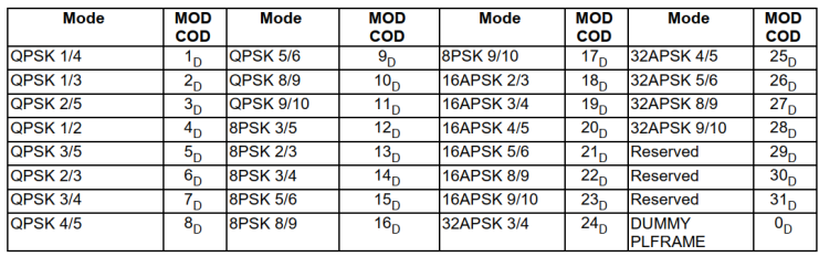
u6 signals the SIZE (0 = normal, 1 = short, not available for FEC 9/10).
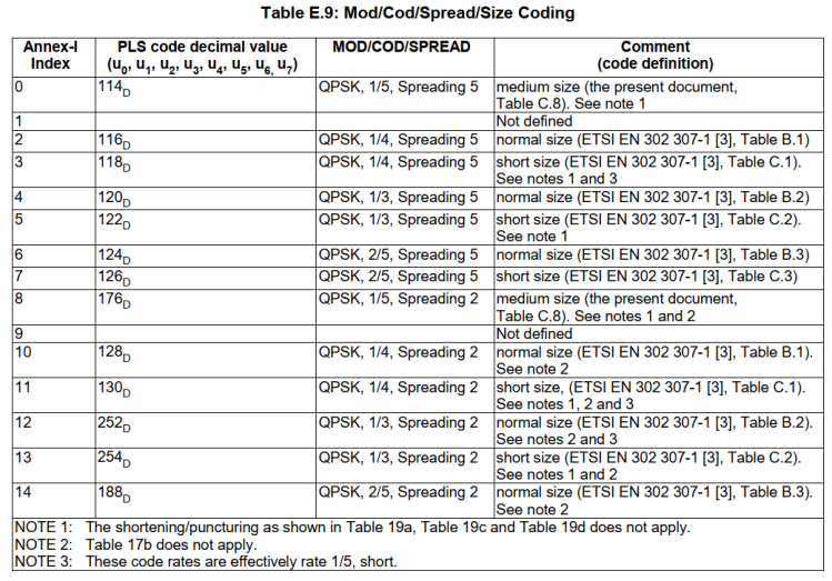
(u0, u1, u2, u3, u4, u5, u6, u7) correspond for decimal value 4D to 113D.
Dummy PL Frame with MODCOD = 0D, PLSCODE = 0D.
If u0 = 1:
(u0, u1, u2, u3, u4, u5, u6, u7) correspond for decimal value 132D to 249D as DVB-S2X MODCOD
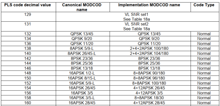
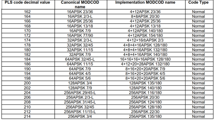
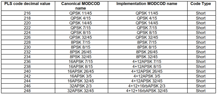
Other PLS values are used from that decimal value range for VL-SNR MODCODS. (overriding the MODCOD settings above, with spreading factor > 1)
8 bits for TSN according to application, refer to Annex M.
Dummy PL frames with deterministic content (TSN = 255)
Dummy PL frame content consists of a sequence of bits representing one FECFRAME derived from a PRBS sequence.
The PRBS sequence is generated by a feed-back shift register with polynomial 1 + x14 + x15, and initial state 100101010000000 (length 215 = 32,767).
Dummy PL frames with arbitrary content (TSN = 254)
The dummy PL frame content can be an arbitrary bit or even symbol sequence selected by the modulator. Not known by the terminal.
Step 2: 16 input bits going through tail-biting convolutional coder (code rate 1/5) to get 80 output bits
Step 3: Block-wise (meaning code-word-wise) repetition with a repetition factor of 2, to get 160 output bits (overall code rate 1/10)
Step 4: As signaled via the SFH, four different PLH protection levels are possible. The spreading factors refer to block-wise repetition. The modulation of the PLSCODE can be BPSK or punctured QPSK.
|
Name |
Ranges |
Note |
|
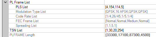
PLS List |
4~255 |
This will be an array, and the length is number of frames. |
|
TSN List |
0~255 |
This will be an array, and the length is number of frames. |
|
PLFRAME Length |
|
This is read-only. The length is the number of frames. This is calculated by PLS in each frame. It will be truncated if the frame is the last one on the waveform. |
In Signal Studio N7623C, the corresponding MOD/COD/SIZE/SPREAD values will be shown with the PLS values in the list. PLFRAME length will be calculated by PLS in each frame.
In the super frame structure, the BB scrambling, FEC encoding and bit mapping into constellation are all the same as in DVB-S2. A PLFRAME is constructed as shown in the following figure before mapping to the CUs of a super-frame. XFECFRAME spreading is signalled via PLH. Spreading factors 1, 2, or 5 are accomplished by frame-wise repetition of the XFECFRAME. XFECFRAMEs with SPREAD > 1 contain additional VL-SNR pilot SLOTs.
|
Name |
Ranges |
Note |
|
BB Scrambling |
Off | On |
Default is Off. The scrambling in defined 5.2.2 in 302 307-1. |
|
Number of PL Frames in Super Frame |
1~100 |
Can be an array when number of super frames is more than one, default is 4 |
The postamble, following the last superframe in a dwell, is constituted of a specific sequence of symbols (pk), 0 ≤ k < L, where:
L = 90, 180, 360 or 900 depending on PLI.
pk = (1-2*bk)(1+j) / sqrt(2) where bk is the k-th bit of the following 900 bits sequence B.
This sequence B can be obtained by concatenating a first PN maximal sequence of 511 bits with polynomial 1+x2+x7+x8+x9 and seed “0 1 1 0 1 1 0 1 1”, concatenated with the first 389 bits of a PN maximal sequence with polynomial 1+x5+x9 and seed “1 0 1 0 1 1 1 0 1”. (511 + 389 = 900)
A sequence of symbols defined as (1 + j)/sqrt(2), the number of which is to be determined by the system implementor to accommodate for hop switching time, synchronization uncertainty and other considerations. This postamble switching sequence is appended after postamble sequence above (length = L).
Finally, the number of symbols in a super frame can be calculated from "Pilot", "Number of CU in Super Frame", "Postamble sequence Length" and "Postamble Switching Length". The result will be shown as an array.
|
Name |
Ranges |
Note |
|
Postamble Sequence Length (L) |
90 | 180 | 360 | 900 |
Read-only. This is defined by PLH Protect Level. This will be an array when the number of super frames is more than one. |
|
Postamble Switching Length |
0 ~ 10000 |
0 means this is not the last SF in the dwell. This can be an array when the number of super frames is more than one. |
|
Number of Symbols in Super Frame (SFL) |
|
Read-only, calculated from "Pilot", "Number of CU in Super Frame", "Postamble sequence Length" and "Postamble Switching Length" |
Super-frame 5 is used for prescheduled beam-hopping. It supports splitting data between two consecutive dwell time of the same cell. There is a parameter “Fragmentation” to set the fragmentation length in CU in the first super frame, a cell destination array to set which cell each SF should be transmitted to, and whether to reset the input bit stream from cell to cell. Then the overflow length for each SF will be shown on GUI. The spilled data will be put in front of the next SF at the same cell. The overflow of the last SF of the cell is discarded.
|
Name |
Ranges |
Note |
|
Fragmentation |
0 ~ First SFL - 720 |
The fragmentation in first super frame. The unit is CU. |
|
Cell Destination |
0~65535 |
Can be an array when the number of super frames is more than one. |
|
Reset Data Input for Different Cell |
True | False |
Default is false. If true, the input stream is reset from cell to cell. |
|
Overflow Length |
|
Read-only. This will be an array when the number of super frames is more than one. |
Super-frame format 6 reuses elements of format 5 with slight modifications:
The modification of SFH to a composite 720 symbols carrying 2 protected bits.
There is no fragmentation of PLFRAMES between super-frames.
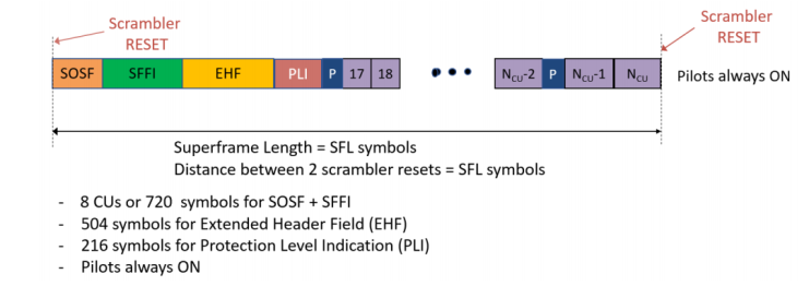

The SFH field shall be comprised of:
Extended Header Field (EHF): 504 fixed symbols.
EHF field will be defined as ith row of the matrix [H252, -H252] where H252=H256(:,3:254). The row and column count start from zero, namely H252 is derived from H256 by removing the first 3 columns and the last column of H256. The same row number (SOSF Sequence Index) shall be selected for the SOSF and EHF fields. The chosen sequence hi is multiplied by (1 + j) / sqrt(2), before reference data scrambling.
PLI (Protection Level Indication) field: 2 information bits mapping to 216 symbols, which signals the PLH protection level.
CPLI sequence as follows:
'00' - A sequence of 216 "0" bits.
'01' - A sequence of 72 "0" bits followed by 144 "1" bits.
'10' - A sequence of 144 "1" bits followed by 72 "0" bits.
'11' - A sequence of 72 "1" bits, followed by 72 "0" bits and concluded with 72 "1" bits
Normalization: multiplied by (-2 * CPLI + 1) * (1 + j) / sqrt(2).