In parameter view windows, you can check
 and
then click the desired parameter for a brief description.
and
then click the desired parameter for a brief description.
The following example procedure shows you how to configure the equipment and Signal Studio software for a typical BER measurement for a fully encoded waveform.
In parameter view windows, you can check
and
then click the desired parameter for a brief description.
From the menu, select .
In the Waveform Setup (DVB-T/H) pane: click n
Edit the parameters to set up a waveform with the following characteristics:

To make flexible BER tests with different configurations (BER tests at different levels), you may re-configure the switches in this step.
In the Tree View: click n
In the Carrier pane: click > (in the right cell click)  >
>
Click > (in the right cell click) 
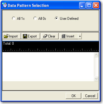
In the Data Pattern Selection Window: Click on
Click option, click on
The length of the truncated PN sequence depends on the RS encoder setting. Since RS encoder ON was previously selected, it is 376 bits for PN9. The purpose of the truncation is to ensure that the PN sequence repeats integer times in the waveform, providing a predictable bit pattern for the BER measurement.
Click to save the truncated PN9 to a specific file, which you can use as the expected data at the receiving end to calculate the BER.
Click to accept the data source configuration.
.
Click the Instrument Settings node in the tree view, set the MXG/EXG/ESG/PSG’s frequency and amplitude to the values below
Frequency: 474 MHz
Amplitude: -50 dBm
From the tool bar, Click  .
.
Notice that a dialog appears to ask you to change the Number of Super Frames. Accept it to ensure that de-scrambler in the receiver works continuously and the truncated PN sequence repeats integer times in the generated waveform.
Observe the message area of the status bar to track waveform generation progress.
When waveform generation is complete, click
 .
.