|
1. DVB-S2 |
2. Payload |
3. MultiPath |
|---|---|---|
| Multi-path Channel | ||
| PCR Offset Frequency | ||
| PCR Offset Amplitude | ||
|
|
||
|
|
Choice: Nyquist \Root Nyquist
Default: Root Nyquist
Double-click or use the drop-down menu to select the filter type.
Conventionally, a data transmission system employs a Nyquist filter whose reply for an impulse is zero (0) for every interval T just before and after a peak (T: data transmission interval). As replies of adjacent data are zero on a sample point of other sampled data, interference between codes can be prevented.
To function as above, a Nyquist filter whose amplitude becomes half at the point where Nyquist frequency fN (=1/2T) is used, and it is odd-symmetrically rolled off with a squared cosine around the half amplitude point in the cutoff area. In this case, the phase characteristics is not considered or is designed to have linear phase characteristics usually.
Instead of a simple Nyquist filter, low-pass filters (root Nyquist filters) having equal amplitude are set for transmission and reception and their characteristics are made the same as that of the Nyquist filter above. In this case, the root Nyquist filter must have cosine characteristics that can be made the squared cosine characteristics above.
Range: 0 to 1
Default: 0.35
Set the roll-off factor for DVB-S2.
DVB-S2 takes into consideration the various requirements of multiple service. For one thing, it supports a wide range of code rate (from 1/4 up to 9/10); for another, roll-off factor can be selected among 0.35, 0.25, 0.2, instead of the fixed 0.35 in DVB-S. With a lower roll-off factor, higher spectrum efficiency can be achieved.
Range: 100 KSymbols/s to 50 (QPSK, 8PSK)/40 (16APSK)/35 (32APSK) MSymbols/s
Default: 10.000000 MSymbols/s
Set the symbol rate for DVB-S2.
The symbol rate is matched to given transponder characteristics, since DVB-S.2 is suitable for use on different satellite transponder bandwidths and frequency bands, and in the case of multiple carriers per transponder (FDM), to the frequency plan adopted.
Choice: 1/4 | 1/3 | 2/5 | 1/2 | 3/5 | 2/3 | 3/4 |4/5 | 5/6 | 8/9 | 9/10
Default: 3/4
Double-click or use the drop-down menu to select the LDPC code rate for DVB-S2.
Choice: QPSK | 8PSK | 16 APSK | 32 APSK
Default: QPSK
Double-click or use the drop-down menu to select the modulation type.
Choice: Normal | short
Default: Normal
Double-click or use the drop-down menu to select whether to use normal LDPC block size or short LDPC block size in DVB-S2.
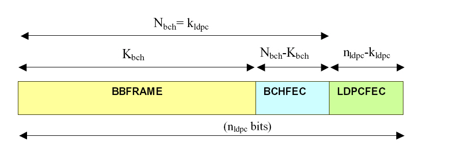
FEC encoding performs outer coding (BCH), Inner Coding (LDPC), and Bit interleaving. The input stream is composed of BBFRAMEs and the output stream of FECFRAMEs. Each BBFRAME (Kbch bits) shall be processed by the FEC coding subsystem, to generate a FECFRAME (nldpc bits). The parity check bits (BCHFEC) of the systematic BCH outer code shall be appended after the BBFRAME, and the parity check bits (LDPCFEC) of the inner LDPC encoder shall be appended after the BCHFEC field, as shown below.
Figure 2 FEC Encoding Data Structure
LDPC encoding provides two kinds of frame length, one is normal frame with length 64800 bit; the other is short frame with length 16200 bit (1/4 of normal frame), shown in the following figure.
Table 1 FECFRAME (normal and short) configurations and application areas
|
System Configuration |
Broadcast Services |
Interactive services |
DSNG |
Professional Services |
|
|---|---|---|---|---|---|
|
FECFRAME(normal) |
64800 (bits) |
N |
N |
N |
N |
|
FECFRAME(short) |
16200 (bits) |
NA |
N |
O |
N |
|
N = normative, O = optional, NA = not applicable. |
|||||
Choice: True | false
Default: True
Double-click or use the drop-down menu to select whether to insert pilot at the physical layer in DVB-S2.
When Insert Pilot is enabled, a PILOT BLOCK composed of P = 36 pilot symbols will be inserted. Each pilot shall be an un-modulated symbol, identified by I = (1/√2), Q = (1/√2). The first PILOT BLOCK shall be inserted 16 SLOTs after the PLHEADER, the second after 32 SLOTs and so on, as represented in figure 13. If the PILOT BLOCK position coincides with the beginning of the next SOF, then the PILOT BLOCK is not transmitted. Besides, the pilot presence/absence in VCM (Variable Coding and Modulation) and ACM (Adaptive Coding and Modulation) can be changed on a frame-by-frame basis.
Choice: Demo File| TS File | NULL TS Packet | Pattern |PN9 | PN15 | PN23
Default:Demo File
Double-click or use the drop-down menu to select which type to use as the data source.
Choice: Local| Instrument
Default: Local
Couplings: Displayed only when the Data Source Type is TS File.
Use "Local" as the File Location and note that "Instrument" is not supported in PXB.
Couplings: Displayed only when the Data Source Type is TS File.
Click  on the right side of the cell to browse your computer and
select the TS file.
on the right side of the cell to browse your computer and
select the TS file.
Choice: NULL Packet Header (0x471FFF10) | SYNC Byte(0x47) | None
Default: SYNC byte (0x47)
Couplings: Displayed only when the Data Source Type is Pattern, PN9, PN15, or PN23.
Double-click or use the drop-down menu to determine whether a SYNC byte (0x47) or a NULL packet header(0x471FFF10) should be inserted into the test pattern.
Couplings: Displayed only when the Data Source Type is Pattern.
Enter the data bits to use in a test pattern.
Choice: On | Off
Default: On
Couplings: Displayed only when the Data Source Type is Demo File or TS File.
Double-click or use the drop-down menu to enable or disable packet stuffing.
Choice: On | Off
Default: On
Couplings: Displayed only when the Data Source Type is Demo File or TS File.
Double-click or use the drop-down menu to enable or disable PCR Adjust.
Range: 0 to 10 MHz
Default: 0.0
Set the frequency for the PCR offset (the offset is calculated by the sin function).
Range: 0 to 10 us
Default: 0
Set the amplitude for the PCR offset (the offset is calculated by the sin function).
Couplings: Displayed only when the Data Source Type is Demo File or TS File.
Displays the useful bit rate for the current setting.
Couplings: Displayed only when the Data Source Type is Demo File or TS File.
Displays the stream bit rate for the current TS file.
Choice: Off | 1 Path | 2 Path | 3 Path | 4 Path
Default: Off
Click on the right side of the cell to open the Multi-path Channel dialog box. Use the dialog box to configure up to 4 static paths. For each path, you can set amplitude attenuation (r), time delay (t [ms]), phase offset (q [rad]), and frequency offset (w [kHz]).